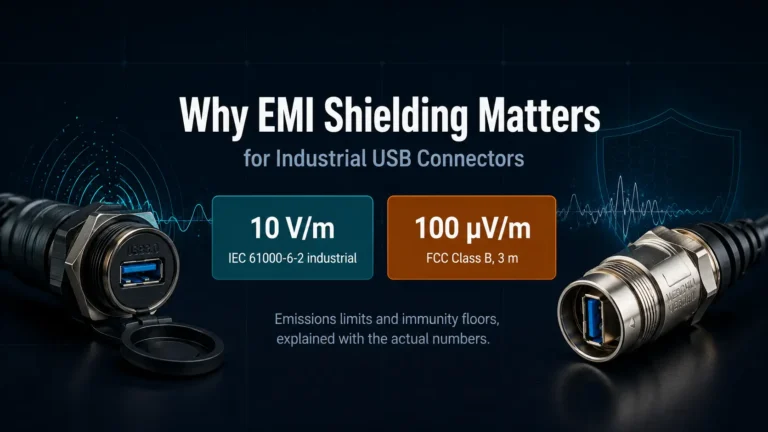
EMI shielding matters on industrial USB connectors because unshielded runs pick up switching noise from VFDs and servo drives and re-radiate it — pushing emissions past FCC’s Class B limit of 100 µV/m at 3 meters (47 CFR §15.109) and leaving the link unable to survive IEC 61000-6-2’s 10 V/m industrial immunity test.
Why does a low-cost USB pigtail need a metal shell and a foil-braid cable when it still passes a continuity test either way? Because continuity says nothing about EMC testing. On a factory floor sharing conduit with VFDs, contactors, and servo drives, an unshielded USB run is both a receive antenna for that noise and a transmit antenna the FCC will measure.
What EMI Actually Does to a Panel-Mount USB Link
Radiated noise from a nearby variable-frequency drive turns its own motor leads into an unintended antenna, and IGBT switching pushes that noise well past 30 MHz — squarely inside the frequency range USB signaling and FCC Part 15 both operate in. Joel Kahn, product manager for inverters at Lenze Americas, told Control Design’s 2018 industry roundtable (retrieved July 21, 2026) that VFD-generated EMI splits into two paths: radiated noise from motor leads acting as antennas, and conducted noise that rides the AC line into anything sharing that circuit. A USB cable routed near a drive cabinet, junction box, or servo amplifier sits in the path of both. Office USB links rarely share a cable tray with kilohertz-switching power cabling; industrial ones often do, which is exactly the noise source USB’s differential-pair signaling was never designed to reject on its own.
Verchil’s USB panel mount types guide covers connector-format selection by port type and use case; this piece focuses on why the shielding spec — not just the connector shape — decides whether that link survives a noisy panel. The same coupling mechanism applies whether the far end is a USB-to-XLR balanced audio run or a straight data pigtail.
How FCC Part 15 Sets the Compliance Bar
Under 47 CFR §15.109, an unintentional radiator — which includes a USB peripheral’s cabling and connector, not just its main board — cannot exceed 100 microvolts per meter in the 30–88 MHz band if it certifies as Class B (residential/light-commercial), measured at 3 meters; a Class A (commercial/industrial) device is measured at 10 meters and capped at 90 µV/m in the same band. Both figures come directly from the FCC’s current rule text (retrieved July 21, 2026) — not a secondary summary.
| Frequency band | Class B limit @ 3 m | Class A limit @ 10 m |
|---|---|---|
| 30–88 MHz | 100 µV/m | 90 µV/m |
| 88–216 MHz | 150 µV/m | 150 µV/m |
| 216–960 MHz | 200 µV/m | 210 µV/m |
| Above 960 MHz | 500 µV/m | 300 µV/m |
Class A and Class B numbers aren’t directly comparable line-by-line, because they’re measured at different distances — a device that reads “looser” in raw µV/m at 10 meters is not automatically a looser real-world source than one measured at 3 meters. What the table does establish is that a USB device’s cabling and connector are inside FCC’s measurement scope at all, which is why panel-mount hardware with a floating or plastic shell fails bench testing even when the board itself is clean. Verchil’s IP65 panel-mount USB connectors use a bonded metal shell specifically so the connector isn’t the open gap in an otherwise-compliant design.
Chart source: 47 CFR §15.109, eCFR current text, retrieved July 21, 2026.
Industrial Immunity Goes Well Beyond What FCC Requires
IEC 61000-6-2 sets the radiated-immunity test level for industrial equipment at 10 V/m across 80–1000 MHz — more than three times the 3 V/m threshold IEC 61000-6-1 sets for residential and light-industrial gear, according to C&L Electronics’ EN 61000-6-2 test summary (retrieved July 21, 2026). FCC Part 15 governs how much noise a device is allowed to emit; IEC 61000-6-2 governs how much noise an installed device has to survive without malfunctioning, and it’s the standard most relevant once a USB run lands inside a control cabinet next to a drive.
| Test | IEC 61000-6-2 (industrial) | IEC 61000-6-1 (residential) | Governing sub-standard |
|---|---|---|---|
| ESD | ±4 kV contact / ±8 kV air | ±4 kV contact / ±8 kV air | IEC 61000-4-2 |
| Radiated RF immunity | 10 V/m, 80–1000 MHz | 3 V/m | IEC 61000-4-3 |
| Conducted RF immunity | 10 Vrms, 0.15–80 MHz | 3 Vrms | IEC 61000-4-6 |
| EFT/burst | ±2 kV power port / ±1 kV signal | ±0.5 kV | IEC 61000-4-4 |
| Surge | ±1 kV L-N / ±2 kV L/N-PE | ±0.5/±1 kV | IEC 61000-4-5 |
| Power-frequency magnetic field | 30 A/m continuous | 3 A/m | IEC 61000-4-8 |
That gap is the practical case for shielding: a USB link that would pass a residential immunity test with an unshielded or lightly-shielded cable can still fail on a factory floor where the ambient RF field and conducted noise are three to ten times higher by design. This is the same environment covered in Verchil’s industrial automation connector solutions page — panel-mount USB is rarely the only signal line in that cabinet, and it’s rarely the best-shielded one by default.
Where Shielding Actually Fails: Braid Coverage and Termination
A standard braided cable shield covers 70–95% of the cable’s circumference, and even premium braids top out around 95% coverage — the gaps in the weave are where high-frequency energy leaks through, not the shield metal itself, according to Hommer Zhao, founder and CEO of Custom Wire Assembly, in the company’s braided-versus-foil shielding comparison (retrieved July 21, 2026). For most industrial applications, 85–90% coverage is the practical balance between shielding effectiveness and cable flexibility; a combination foil-plus-braid construction closes most remaining gaps and pushes effective coverage close to 100%, at the cost of a stiffer, less flexible cable.
Coverage percentage only pays off if the shield actually terminates somewhere with low impedance. Romtronic’s guide to 360° shield termination methods (Sam Wu, published October 2025, retrieved July 21, 2026) lists braid-cone inserts, mechanical clamp/band termination, and solder-sleeve termination as the three common ways to ground a shield fully around its circumference rather than through a single drain wire — a full-circumference ground path keeps impedance low across a wide frequency range, where a pigtail-style drain wire acts as an inductor at higher frequencies and lets exactly the energy a good braid caught leak back out at the connector. That’s the same principle Verchil’s USB-C panel mount guide touches on when it notes that a floating connector shell becomes its own EMI antenna — the cable can be well shielded and still lose to a poor termination at the connector end.
What to Check on a Panel-Mount USB Connector’s Spec Sheet
A metal connector shell that isn’t bonded to the panel with continuous contact around its full circumference is a gap in the shield path regardless of the cable’s own coverage percentage — which is why Verchil’s IP65 panel-mount USB connectors specify a Zinc Diecast metal shell rather than plastic, achieving over 500 MΩ insulation resistance across more than 500 mating cycles. None of that is a substitute for a properly shielded, correctly terminated cable — a metal shell with an unshielded cable behind it still radiates from the exposed run — but a plastic shell removes the termination point entirely, no matter how good the cable is.
For teams weighing environments rather than debating one spec in isolation, the matrix below is Verchil’s own synthesis of the FCC, IEC, and termination data already covered above — mapped to installation conditions rather than reproduced from any single manufacturer’s table:
Verchil’s environment-to-shield-spec matrix
| Installation environment | Likely FCC class | Braid coverage target | Termination | Shell requirement |
|---|---|---|---|---|
| Office/desk, no drives nearby | Class B (residential/light-commercial) | 70–85% acceptable | Single-end OK for short runs | Plastic or metal |
| Control cabinet near VFD/servo, indoor | Class A + IEC 61000-6-2 immunity | 85–90% minimum | 360° both ends (braid cone/clamp/solder sleeve) | Metal, bonded to panel |
| Cabinet with outdoor or washdown exposure | Class A + IEC 61000-6-2 + ingress rating | 90–95%+ or foil-plus-braid combo | 360° both ends, sealed gland | Metal, IP65+, bonded |
Four things worth checking before specifying a panel-mount USB connector for a cabinet that shares space with drives or contactors: shell material (metal, not plastic, for a bondable ground path), whether the datasheet states a braid coverage percentage or just says “shielded” with no number, whether the panel-mount flange is designed to bond to bare metal rather than painted or anodized panel finish, and whether the housing carries an ingress rating like IP65 — not because IP65 itself is an EMI spec, but because a sealed metal housing typically implies the same continuous-contact design that a good ground path needs. Verchil doesn’t publish a shielding-effectiveness dB figure for these connectors and won’t invent one here; the honest claim is the metal shell, the bonding path, and the mating-cycle and insulation-resistance numbers above, all pulled from the current USB panel mount connector and panel mount USB socket specs.
EMI shielding on an industrial USB connector isn’t one spec — it’s a chain: cable braid coverage, 360° termination at the connector shell, a metal shell bonded to a grounded panel, and enough margin against IEC 61000-6-2’s 10 V/m immunity floor to survive a real drive cabinet. Skip any one link and the FCC Part 15 numbers on a datasheet don’t guarantee a quiet installation. Verchil’s IP65 panel-mount USB connectors use a Zinc Diecast metal shell and gold-plated contacts built for that kind of duty — talk to our engineering team about a specific cabinet layout, or reach us directly on WhatsApp with the panel spec.
Frequently Asked Questions
Does a shielded USB cable alone make a connector EMI-compliant?
No — the cable’s shield only helps if it terminates to the connector shell with continuous contact, and the shell itself must bond to a grounded metal panel. A shielded cable plugged into a plastic-shell connector, or a metal shell isolated from panel ground by paint or plating gaps, leaves the shield path open exactly where it matters most.
Should a USB shield be grounded at one end or both ends?
For panel-mount industrial runs, terminate the shield at both connector ends with a 360° connection — braid cone, clamp, or solder sleeve — instead of a single pigtail drain wire, so the shield forms one continuous low-impedance path rather than depending on a single ground point. Single-end grounding is common practice for sensitive low-frequency analog wiring; industrial USB runs sharing conduit with drives benefit from full-circumference termination at both ends.
What’s the difference between FCC Class A and Class B limits for USB devices?
Class B covers residential and light-commercial equipment, tested at 3 meters with a 100 µV/m limit at 30–88 MHz; Class A covers commercial/industrial equipment, tested at 10 meters at 90 µV/m in the same band, under 47 CFR §15.109. Most general-purpose panel-mount USB peripherals certify Class B; equipment built into industrial control cabinets often certifies Class A.
Can EMI from a VFD actually corrupt USB data, or does it just cause noise?
Both, depending on level. Below the immunity threshold, USB’s differential signaling and error-checking usually absorb minor noise with no visible fault. Above it — commonly past the 10 V/m industrial floor set by IEC 61000-6-2 — links can drop packets, disconnect, or fail to enumerate, especially on longer panel-mount runs near drive cabinets.
Does braid coverage percentage matter more than shield material?
Coverage matters most for high-frequency leakage. A 95%-coverage copper braid blocks more RF than a lower-coverage version of the same material, because gaps in the weave — not the metal itself — let energy through; a combination foil-plus-braid shield closes those gaps for effective coverage near 100%.
Is a metal connector shell required, or does a shielded cable do the job on its own?
A shielded cable needs somewhere to terminate its shield with low impedance, and a plastic connector shell gives it nowhere to go. That’s why industrial panel-mount USB connectors typically specify a metal shell bonded to a grounded panel, rather than relying on cable shielding alone.