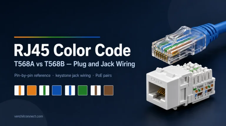
T568A and T568B are the two RJ45 wiring standards defined under ANSI/TIA-568. Both are electrically equivalent; the orange and green pairs simply swap positions across pins 1, 2, 3, and 6. T568B is the more common choice in commercial installs. Pick one standard and use it on both ends of every cable.
Ever crimped a plug to match the T568B color chart, then popped open a keystone jack and found the wires landing in what looks like the wrong order entirely? You didn’t wire it wrong. RJ45 termination actually involves two different physical jobs — a plug’s flat, sequential contacts and a jack’s staggered internal wiring — and most color-code guides only show you the first one. This page covers both: the full T568A/T568B pin table, when a crossover cable still matters, why jack wiring looks different from the plug chart, and which wires carry power under PoE.
T568A vs T568B Color Code: The Pin-by-Pin Reference Table
T568A and T568B are the two RJ45 wiring standards under ANSI/TIA-568, differing only in which pins carry the orange and green pairs — everything else about the eight-position layout is identical (Wikipedia, “8P8C,” last edited 2026-07-05, retrieved 2026-07-20; corroborated by Fluke Networks, “T568A vs T568B,” retrieved 2026-07-20, which confirms the same pin 1/2 vs pin 3/6 orange-green swap).
| Pin | T568A Pair | T568A Color | T568B Pair | T568B Color |
|---|---|---|---|---|
| 1 | 3 | White/Green | 2 | White/Orange |
| 2 | 3 | Green | 2 | Orange |
| 3 | 2 | White/Orange | 3 | White/Green |
| 4 | 1 | Blue | 1 | Blue |
| 5 | 1 | White/Blue | 1 | White/Blue |
| 6 | 2 | Orange | 3 | Green |
| 7 | 4 | White/Brown | 4 | White/Brown |
| 8 | 4 | Brown | 4 | Brown |
Pins 4, 5, 7, and 8 — the blue and brown pairs — are identical in both standards. Only pins 1, 2, 3, and 6 swap, because the orange and green pairs trade places. That overlap matters later in this guide: it’s the same reason PoE Mode B can run on a cable regardless of which standard terminates it. For the background on why two competing standards exist in the first place and when each one originated, our full RJ45 connector guide covers the broader form factors, gender, and cable-category side of RJ45 beyond just the color code.
Most commercial installers default to T568B unless a legacy telephone system or an existing building standard specifies T568A. The only wrong answer is switching mid-project — pick one and terminate every jack and plug in the run to match.
Straight-Through vs Crossover: How the Color Code Changes at Each End
A cable wired T568A on one end and T568B on the other becomes a crossover cable — reversing the transmit and receive pairs so two similar devices can talk to each other directly, without a switch in between (Wikipedia, “8P8C,” last edited 2026-07-05, retrieved 2026-07-20).
A straight-through cable uses the same standard on both ends; a crossover cable deliberately mixes them. Before Auto-MDI-X became standard, crossover cables solved a specific problem: connecting two PCs directly, or linking two switches or hubs together, required swapping the transmit and receive pairs somewhere in the path. Auto-MDI-X — defined under IEEE 802.3 and built into most network interface cards sold today — detects the cable type on connection and swaps the pairs internally instead, which is why a straight-through cable now works in almost every situation a crossover cable used to be required for.
That “almost” still matters in a few corners of industrial and legacy networking. Older unmanaged switches, some fixed-function serial-to-Ethernet converters, and certain PLC network interfaces don’t implement Auto-MDI-X, so a direct connection between two of them can still need a genuine crossover cable. If you’re troubleshooting a link that won’t come up between older equipment, checking whether both ends support Auto-MDI-X is worth doing before you start second-guessing the color code. For the broader landscape of jack types, panel parts, and where each one fits in a build, browse the network connector category.
Why a Keystone Jack’s Internal Wiring Doesn’t Match the Plug Color Chart
A keystone jack’s internal wiring rarely mirrors the front-view color chart, because most jacks route each pair through an internal circuit board and stagger the insulation-displacement contacts across multiple rows specifically to cut crosstalk (Fluke Networks, 2014, retrieved 2026-07-20; US Patent 6,582,247, 2003, retrieved 2026-07-20).
A crimped plug is the simple case: eight flat contacts sit in a row, and the color you push into slot 1 is electrically pin 1. A keystone jack is a different mechanism entirely. It terminates wire with insulation-displacement contacts (IDCs) — small metal blades that cut through the wire’s insulation instead of requiring a stripped end — and Fluke Networks notes plainly that “the wiring at the rear of the jack varies by manufacturer and may not be in the same sequence as the front,” because that routing runs through a small printed-circuit board inside the jack assembly.
That’s not a manufacturing shortcut. A US patent covering IDC connecting-block design describes contacts “positioned in multiple staggered rows for the purpose of minimizing crosstalk” — the physical stagger is there to keep adjacent pairs from picking up each other’s signal, the same electrical goal that drives twisted-pair cable design in the first place. Insulation-displacement connection itself works by cutting metal through the wire’s insulation to make contact without stripping it first, a termination method used broadly across structured cabling and industrial wiring, not something unique to any one jack brand.
The practical takeaway: don’t assume a jack’s punch-down layout will visually match the plug diagram you just used. Follow the color-coded labels printed on that specific jack — quality jacks mark both T568A and T568B color dots at each terminal — and confirm the run with a continuity or wire-map tester after termination rather than trusting a visual comparison to the plug chart. That’s also why panel-mount and pre-terminated jacks — including Verchil’s panel-mount waterproof RJ45 jacks — get continuity-tested at the factory rather than leaving pin-to-pair mapping to field wiring.
PoE and Industrial Wiring: What Changes When the Cable Carries Power
IEEE 802.3af/at PoE Mode B delivers power on pins 4, 5, 7, and 8 — the blue and brown pairs untouched by 10/100 Mbps data — while Mode A shares the data pairs on pins 1, 2, 3, and 6 instead (Wikipedia, “Power over Ethernet,” last edited 2026-07-14, retrieved 2026-07-20; corroborated by Bel, “Power Over Ethernet Explained,” retrieved 2026-07-20, which confirms the same Mode A pins 1/2/3/6 vs Mode B pins 4/5/7/8 split).
Mode A and Mode B exist because early PoE had to work over cabling that was already carrying 10BASE-T or 100BASE-TX data, which only uses two of the four pairs. Mode B puts power on the two pairs data wasn’t using — pins 4-5 and 7-8 — which keeps power and data electrically separate and makes field troubleshooting easier. Mode A instead runs power on the same data pairs, using a technique similar to phantom power in professional audio, with polarity handled through a diode bridge since a crossover cable could otherwise flip it. Once a link moves to Gigabit or faster — 1000BASE-T, 2.5GBASE-T, 5GBASE-T, 10GBASE-T — there are no spare pairs left, so 4-pair PoE (IEEE 802.3bt) delivers power across all four pairs simultaneously instead of choosing one mode.
That distinction has a direct payoff on a factory floor or a comms room: if a PoE camera or access point loses power but the data link still looks fine on a basic tester, checking whether the device runs Mode A or Mode B narrows down which physical pins to test first, rather than re-terminating the whole jack. For multi-device PoE deployments — IP cameras, wireless access points, or PLC network interfaces spread across a plant — industrial automation connector solutions built for that environment save the trial-and-error of retrofitting standard office-grade parts into a washdown or high-vibration area.
The 3-Layer RJ45 Wiring Check
Put together, the color code, the cable type, and the termination method are three separate questions — and mixing them up is the most common source of “why doesn’t this link work” troubleshooting. Before calling a run good, check all three:
| Layer | Question | What to verify |
|---|---|---|
| 1. Standard | T568A or T568B? | Same standard on both ends, unless you’re intentionally building a crossover cable |
| 2. Cable type | Straight-through or crossover? | Auto-MDI-X handles most modern gear automatically; verify manually only for older or fixed-function equipment |
| 3. Termination | Plug crimp or jack IDC? | Don’t assume the jack’s internal layout visually matches the plug chart — follow the jack’s own printed color dots and confirm with a continuity test |
Conclusion
T568A and T568B differ only in where the orange and green pairs land — the rest of the eight-pin layout, including PoE’s Mode A and Mode B power pairs, stays identical. The part most color-code guides skip is termination: a plug’s flat contacts and a jack’s staggered IDC rows are two different physical jobs, and matching colors on one doesn’t guarantee the other is right without a continuity check. For outdoor, industrial, or high-vibration deployments where a field-wiring mistake is costly, Verchil’s panel-mount and waterproof RJ45 connectors ship factory-tested — request a quote or check specs on WhatsApp.
FAQ
Should I wire T568A or T568B?
Either works — they’re electrically equivalent. T568B is the more common default in commercial installs; T568A keeps compatibility with some older telephone wiring. The rule that actually matters is consistency: use the same standard on both ends unless you’re intentionally building a crossover cable.
What’s the actual difference between T568A and T568B?
Only the orange and green pairs swap position, across pins 1, 2, 3, and 6. Pins 4, 5, 7, and 8 — the blue and brown pairs — are identical in both standards, which is also why they’re the pairs used for PoE Mode B power.
Do I still need a crossover cable?
Rarely. Auto-MDI-X, standard on most network interface cards under IEEE 802.3, detects the cable type and swaps transmit/receive pairs automatically. Crossover cables still matter for some older or fixed-function gear — certain industrial switches and legacy hubs — that doesn’t support Auto-MDI-X.
Which wires carry power in PoE?
It depends on the mode. PoE Mode B uses the spare pairs on pins 4-5 and 7-8 (blue/brown); Mode A shares the data pairs on pins 1-2 and 3-6 instead. Four-pair PoE (802.3bt) for Gigabit and faster links uses all four pairs at once, since there are no spare pairs left to dedicate to power.
Why does my keystone jack’s wiring look different from the plug color chart?
Because it’s a different physical job. A plug’s contacts sit flat and sequential; a jack routes each pair through insulation-displacement contacts staggered across multiple rows to cut crosstalk. Follow the color-coded dots printed on that specific jack, not the plug diagram, and test continuity after punching down.
What happens if I mix T568A and T568B on one cable?
By accident, it becomes an unintentional crossover, which can cause a failed or unreliable link between two devices that both expect a straight-through cable. Auto-MDI-X catches many of these mistakes on modern equipment, but it isn’t guaranteed on every device, so consistency still matters.
Should I wire my own RJ45 jack or buy a pre-terminated one?
For a low-risk indoor run, wiring your own is fine and cheaper. For outdoor, high-vibration, or PoE-industrial deployments, a factory-terminated and sealed connector removes the wiring-order risk and the chance of moisture reaching an exposed IDC connection — worth the added cost in those environments.