A 3-pin XLR connector is the standard balanced audio connector used for microphones, mixers, and professional audio gear. Pin 1 carries the ground/shield, Pin 2 the hot (+) signal, and Pin 3 the cold (−) signal. This balanced design rejects noise over runs past 100 m and carries +48V phantom power for condenser microphones.
Ever plugged a microphone into a mixer, connected a stage monitor, or built a PA system? Whether you realized it or not, you were using a 3-pin XLR connector — the foundational core of professional audio, broadcast, and live performance. Because most users never look past the plug itself, this guide breaks down what really matters: the pinout, why it delivers such clean sound, and how to choose, solder, and troubleshoot 3-pin XLR connectors like a professional.
What Is a 3 Pin XLR Connector?
The 3-pin XLR connector is a circular, locking balanced-audio connector used across professional and semi-professional audio equipment. Developed by Cannon Electric (now ITT Cannon) in the 1950s, it’s internationally standardized under IEC 60268-12. Because its three pins sit in a rugged metal housing with a safety latch, it resists accidental disconnection — critical in live performance.
The name comes from Cannon’s original line: the “X” series gained a Latch and a Rubber compound, becoming XLR. Because the 3-pin version is by far the most common, you’ll find it everywhere — from condenser microphones to stage snake cables and studio patchbays. For the full connector history and all pin variants, see our XLR connector guide.
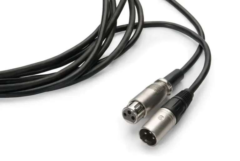
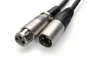
Male vs Female 3-Pin XLR
- Male XLR (exposed pins) — at the output end: microphones, DI boxes, and some audio interfaces
- Female XLR (recessed sockets) — at the input end: mixers, preamps, and power amplifiers
- Cable-mount vs chassis-mount — Because some connectors terminate a cable while others mount on a panel, cable-mount types attach to the cable end, while chassis-mount types are soldered or screwed onto the equipment panel
Because signal always flows from male pins into female sockets, the direction never varies. For full detail, see our XLR male connector guide and XLR female connector guide.
3 Pin XLR Pinout: What Each Pin Does
Per Shure’s balanced audio wiring reference, the standard 3-pin XLR pinout (IEC 60268-12) assigns:
| Pin | Signal | Function | Wire Color (typical) |
|---|---|---|---|
| Pin 1 | Ground / Shield | Chassis ground; carries the shield to block interference | Bare / black |
| Pin 2 | Hot (+) | Positive phase of the balanced signal | Red / white |
| Pin 3 | Cold (−) | Inverted phase of the balanced signal | Blue / black |
💡 Pro tip — the memory aid: “2 is hot, 3 is not.” Pin 2 sends the signal in positive phase; Pin 3 carries the inverted copy.
What Happens If You Wire It Wrong?
Because reversing Pin 2 and Pin 3 flips the polarity, the error is usually inaudible on a single cable — but when that cable is mixed with a correctly-wired one, the two signals partially cancel, producing thin, hollow, bass-light audio. Before soldering, always verify the pinout. For complete pin-by-pin diagrams across all XLR variants, see our XLR connector pinout guide.
Why the 3 Pin XLR Delivers Clean Audio: Balanced Signaling
The 3-pin XLR’s core advantage is its balanced connection. Unlike an unbalanced TS connector that carries one signal copy, the XLR cable transmits two copies — one in-phase (Pin 2), one inverted (Pin 3).
How Balanced Audio Rejects Noise
- At the source, the signal splits into two opposite-phase copies.
- Both travel the cable together (Pin 2 and Pin 3).
- Because any electromagnetic interference hits both wires equally, it appears identically on each.
- When the receiver flips Pin 3 back to normal phase, the noise it picked up inverts and cancels — while the wanted signal doubles.
This is called common-mode rejection (CMR). Because CMR cancels noise so effectively, a 3-pin XLR cable runs past 100 m through electrically noisy stages or wall-filled cable runs without audible hum — where an unbalanced cable would be unusable.
This is called common-mode rejection (CMR); proper Pin 1 shield grounding follows AES48, the AES standard on grounding and EMC.
5 Real-World Uses of the 3 Pin XLR Connector
The 3-pin XLR appears in five core settings — microphones, mixers, stage snakes, studio patchbays, and broadcast routing — all sharing one trait: balanced, lockable connections that survive daily abuse.
Microphone
Microphone XLR connector is the most common application scenario. Because both dynamic and condenser microphones terminate in a male XLR, they plug into the female XLR input on a mixer. When a condenser microphone is connected, it also draws +48V phantom power through Pin 2 and Pin 3 — a unique XLR capability no unbalanced connector can match.
it also draws +48 V phantom power through Pin 2 and Pin 3, as defined by IEC 61938 (the phantom-powering standard).
Mixers and Preamps
Every professional mixing console, from the compact Yamaha MG series to large-format SSL or API desks, has a female XLR input on each channel. Because the latch locks the cable in place, it won’t fall out during a performance or recording.
Stage Snake & Multicore Cable
A stage snake bundles multiple XLR cable runs into a single multicore sheath, running from stage to the front-of-house mix position.
Recording studio wiring board
The studio uses the XLR wiring board to flexibly route between the external effector, the preamplifier and the audio interface, without permanent rewiring of the studio. The robust structure of the interface can withstand hundreds of insertion and extraction operations per day.
Broadcasting and audio-visual fixed system
TV studios, carts, and permanent audiovisual mounting systems all rely on XLR routing due to its robust noise immunity over long-distance cables, as well as standardized pin definitions – allowing any device to plug and play with other devices.
Beyond Audio: Other 3-Pin XLR Uses
Although audio is its main domain, the 3-pin XLR also appears outside the studio:
- Electric wheelchairs and mobility scooters — many use 3-pin XLR connectors for battery-charger connections, valued for their rugged locking design.
- Low-end DMX lighting — some entry-level fixtures use 3-pin XLR for DMX512 data, though 5-pin is the proper standard (see our 5 Pin XLR Connector Guide) — never share audio and DMX cables.
- Intercom and RS-485 data — certain industrial and automation systems (e.g. Crestron Cresnet) use 3-pin or 4-pin XLR for long-distance data runs.
Because the same rugged, locking 3-pin format serves all these roles, always confirm a cable’s intended use before connecting — a charger cable and a mic cable may look identical but carry very different signals.

3 Pin XLR vs TRS, RCA & TS: Quick Comparison
| Feature | 3 Pin XLR Connector | TRS (1/4″) | RCA / Phono | TS (Unbalanced) |
|---|---|---|---|---|
| Balanced signal | ✅ Yes | ✅ Yes (TRS) | ❌ No | ❌ No |
| Locking mechanism | ✅ Yes | ❌ No | ❌ No | ❌ No |
| Phantom power (+48V) | ✅ Yes | ❌ No | ❌ No | ❌ No |
| Cable run length | 100m+ | ~15m (balanced) | ~5m | ~5m |
| Common use | Microphones, live audio | Headphones, instruments | Consumer hi-fi | Guitar cables |
| Noise immunity | Excellent | Good (when balanced) | Poor | Poor |
Because the 3-pin XLR is the only option here with a locking latch, phantom power, and 100m+ balanced runs, it remains the professional standard. For TRS comparison detail, see our TRS connector guide; for XLR-to-TRS conversion, see our XLR to TRS cable guide.
How to Solder a 3 Pin XLR Connector: Step-by-Step
Self-made XLR cable is a cost-effective skill that every audio professional should master. The following is the basic process for welding a standard balanced audio connection:
Tools and materials required
- Male and female XLR cable installation interface
- Balanced Microphone Cable (Double Core + Shield)
- Electric soldering iron (25-40W) and soldering tin (60/40 rosin core)
- Stripping pliers and small screwdriver
- Heat shrinkable tube (optional, but highly recommended)
These are typical values; for iron temperature, cold-joint identification and rework, follow our solder XLR connector guide (aligned with IPC J-STD-001 soldering acceptance criteria).
Step-by-Step Soldering
Because forgetting the shell is the most common mistake, start there:
- Slide the connector shell onto the cable first — before any soldering.
- Strip about 25 mm of outer jacket, then twist the shield braid into a single strand.
- Strip about 5 mm of each inner conductor.
- Pre-tin all conductors with a little solder.
- Solder Pin 1 — shield / ground (bare wire).
- Solder Pin 2 — positive phase (red or white).
- Solder Pin 3 — negative phase (blue or black).
- Assemble the shell and tighten the strain-relief clamp.
- Before connecting valuable gear, test continuity with a cable tester.
For the complete soldering technique — iron temperature, cold-joint identification, and star-quad wiring — see our dedicated solder XLR connector guide.
How to Choose a 3 Pin XLR Connector
Choosing a 3-pin XLR comes down to three factors: build quality, cable-diameter fit, and cable-mount vs chassis-mount — get these right and a connector lasts hundreds of mating cycles.
Quality of workmanship and brand selection
Neutrik is recognized as the industry benchmark for its color sheath system, strong locking mechanism and oxidation-resistant gold-plated contacts. Other trusted brands include Verchil, Amphenol and Switchcraft. Key applications should avoid using unbranded low-cost interfaces-the contact resistance of cheap interfaces will introduce noise over time.
Cable diameter compatibility
Please verify the cable entrance size of the interface before purchase. If the too thick cable is designed for the use of the interface of the finer cable, the stress release effect will be poor, and finally the cable at the interface will be broken.
Cable installation vs. Chassis installation
Cable mounting type (NC3MXX/NC3FXX): Standard selection of self-made cables.
Case mounting D series (NC3MD-L/NC3FD-L): Panel mounting for custom equipment, rack units and stage junction boxes.
3 Pin XLR Troubleshooting: 3 Common Faults
Hum or Buzz
Because most hum traces to a ground loop (two devices sharing ground at different potentials), fix it by using a DI box with a ground-lift switch, confirming Pin 1 is properly soldered to the shield, or inserting a hum isolator (isolation transformer) in the signal path.
Intermittent Signal or Dropouts
Because intermittent faults almost always point to cold solder joints on Pin 2 or Pin 3 (or a broken wire near the cable entry), open the connector, inspect with a magnifier, and reflow or replace the joint.
Latch Won’t Lock
When the locking latch is worn or bent, the connector won’t lock. For Neutrik connectors, the latch spring is a replaceable part (Neutrik offers a repair kit); for other brands, replace the whole connector.
Frequently Asked Questions
Can 3 pin XLR connector be used for stereo audio?
No. A single 3-pin XLR can only carry one balanced single-channel signal. If you need to transmit stereo, you need two XLR cables (one per channel), or use a 5-pin XLR interface. This format is used for some intercom and headphone systems, and stereo can be transmitted through a single interface.
What Is Phantom Power, and How Does XLR Support It?
Phantom power is +48V DC supplied by a mixer or preamp through Pin 2 and Pin 3 to power condenser microphones and active DI boxes. Because the balanced design applies the voltage equally to both pins, it cancels out in the audio path — meaning it has no audible effect on dynamic microphones that don’t need it.
Is there any difference between 3 pin XLR connector and XLR-3?
These two terms can be used interchangeably. ‘XLR-3’ only explicitly specifies a 3-pin variant to distinguish it from the 4-pin XLR (for some headphones and LED luminaires) and 5-pin XLR (for DMX light control and specific stereo headphones) in the same interface family.
Can a 3 pin XLR connector be connected to a TRS or RCA connector?
Yes, it can be achieved using adapters or dedicated adapter cables. XLR to TRS adapters are often used to connect balanced microphone signals to civil or semi-professional devices with TRS inputs. The XLR to RCA adapter can convert the balanced signal into an unbalanced signal – because the balanced signal is usually about 6dB higher than the unbalanced signal, the signal level may need to be adjusted.
Is a 3-pin XLR connector the same as a standard XLR?
Yes — in everyday audio, “XLR connector” almost always means the 3-pin version. Because the 3-pin XLR is by far the most common variant, the terms are used interchangeably. The XLR family also includes 4-pin, 5-pin, 6-pin, and 7-pin variants for intercom, DMX, and specialty uses — see our XLR connector pinout guide for all variants.
What wire gauge should I use with a 3-pin XLR connector?
Most balanced microphone cables use 22–24 AWG inner conductors. Because thicker conductors lower resistance on long runs, 22 AWG suits runs over 15 m, while 24 AWG is fine for shorter patch cables. Before buying a connector, confirm its strain relief fits your cable’s outer diameter.
Can I use a 3-pin XLR cable for DMX lighting?
It’s not recommended. Although some entry-level fixtures accept 3-pin XLR for DMX, the proper DMX standard is 5-pin with 110-ohm cable. Because microphone cable has the wrong impedance (45–75 ohm), using it for DMX causes flicker and dropouts on longer runs. Keep audio and DMX cables clearly separated. Keep audio and DMX cables separate — for correct DMX wiring see the 5 Pin XLR Connector Guide.
Why the 3 Pin XLR Remains the Professional Standard
Because decades of digital innovation — from wireless systems to audio-over-IP — still haven’t replaced it, the 3-pin XLR endures. Its locking shell, noise-rejecting balanced path, phantom power capability, and industry-wide standardized pinout make it irreplaceable where reliability can’t be compromised.
Whether you’re wiring your first studio microphone, building a custom stage box, or troubleshooting a noise problem, mastering the 3-pin XLR is one of the most valuable skills an audio professional can build.
Explore our companion guides: XLR connector guide, XLR connector pinout, 4 Pin and 5 Pin XLR guides, and the solder XLR connector guide. For custom 3-pin XLR assemblies and bulk orders, contact our technical team.
