The standard 3-pin XLR pinout is Pin 1 = Ground/Shield, Pin 2 = Hot/Positive (+), Pin 3 = Cold/Negative (−), defined by AES14-1992 (internationally IEC 60268-12). This “Pin 2 hot” wiring is universal across professional audio worldwide.
Soldering a microphone cable and unsure which wire goes to which pin? Hearing hum on a line you wired yourself? Whether you build home studios, repair mic cables, or run live stages, getting the XLR connector pinout right is the foundation of clean, noise-free audio. This page is your wiring-diagram reference for every XLR variant — with a fault-finding section at the end.
Why XLR Pinout Matters for Balanced Audio
An XLR connector is a locking circular connector used for balanced audio, microphone inputs, and stage systems — and balanced wiring rejects noise precisely because Pin 2 and Pin 3 carry the same signal in opposite polarity. The receiver subtracts the two and any interference picked up equally on both (common-mode hum) cancels out. This is why pin assignment, not just cable quality, determines whether a line is quiet. For the full connector overview, see our XLR connector guide; the grounding behavior here follows AES48 (the AES standard on grounding and EMC).
Balanced vs unbalanced wiring at a glance
| Feature | Balanced (XLR) | Unbalanced (TS / RCA) |
|---|---|---|
| Conductors | 3 (Hot, Cold, Ground) | 2 (Signal, Ground) |
| Noise rejection | Excellent (common-mode rejection) | Poor |
| Long cable runs | Yes — 300 ft and beyond | No — about 15–20 ft max |
| Phantom power | Yes (+48 V) | No |
| Common use | Mic, stage, studio, broadcast | Guitar, home stereo, DJ gear |
| Connector type | XLR (3-pin and up) | 1/4-inch TS, RCA, 3.5 mm |
Standard 3-Pin XLR Pinout (AES14-1992 Wiring)
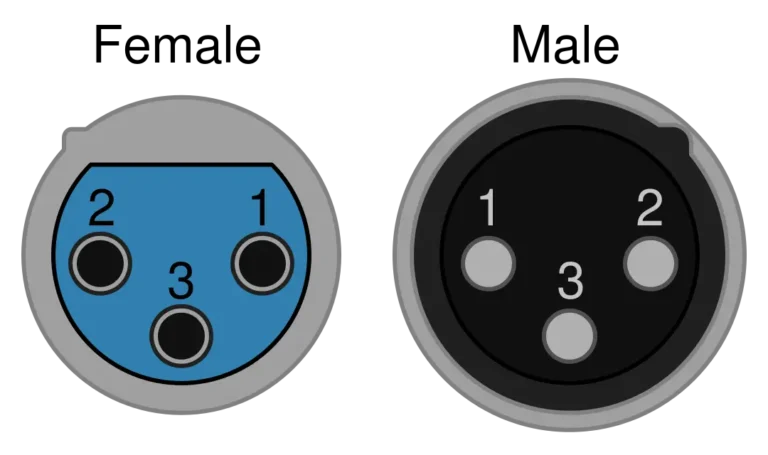
The 3-pin XLR is the most common variant, and its pinout never changes: Pin 1 = Ground, Pin 2 = Hot (+), Pin 3 = Cold (−) per AES14-1992 (international equivalent IEC 60268-12).
Reading the connector — male vs female: the female is a mirror image of the male, so the physical arrangement looks reversed even though the numbering is identical. Always check the pin numbers molded into the plastic insert next to each contact.
💡 “X-L-R” memory trick: X (eXternal/shield) = Pin 1, L (Live/hot) = Pin 2, R (Return) = Pin 3 — or the engineer’s rhyme “one is ground, two is hot, three is not.”
For full 3-pin wiring, applications, soldering and selection, see our complete 3 Pin XLR Connector Guide and the XLR male connector guide.
| Pin Number | Function | Typical Wire Color | Description |
|---|---|---|---|
| Pin 1 | Ground / Shield | Bare wire / drain | Connects to cable shield and chassis ground |
| Pin 2 | Hot / Positive (+) | Red or white | Carries the in-phase signal |
| Pin 3 | Cold / Negative (−) | Black or blue | Carries the inverted (180°) signal |
Why Pin 2 Hot Became the Global Standard
Before AES14-1992 standardized “Pin 2 Hot,” chaos reigned: some American manufacturers wired “Pin 3 Hot,” while Europe and Japan used “Pin 2 Hot.” When the two standards were mixed, the result was phase cancellation — thin drum overheads and hollow-sounding guitars. Since AES14-1992 (later ANSI S4.48) ended the confusion, Most modern professional audio equipment follows the Pin 2 Hot convention. If you connect to vintage Pin 3 Hot equipment, swap Pin 2 and Pin 3 at one cable end only.
4-Pin, 5-Pin, 6-Pin & 7-Pin XLR Pinout Variants
Beyond the 3-pin standard, four larger variants each serve a distinct job. The key rule: more pins means more independent signal paths, not a “better” connector — pick by application, never by pin count.
4-pin XLR — intercom headsets and camera DC power. Intercom (Clear-Com/RTS/Telex): Pin 1 mic ground, Pin 2 mic (+), Pin 3 headphone ground, Pin 4 headphone (+). Camera DC: Pin 1 = Ground, Pin 4 = +12 V. Full wiring and intercom-brand pinouts → 4 Pin XLR Connector Guide.
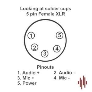
5-pin XLR — DMX512 lighting and stereo audio. DMX: Pin 1 shield, Pin 2 Data 1−, Pin 3 Data 1+, Pin 4 Data 2−, Pin 5 Data 2+. True DMX requires 110-ohm cable, not a mic cable — per ESTA E1.11 (USITT DMX512-A). Full DMX wiring, daisy-chain and termination → 5 Pin XLR Connector Guide.
6-pin & 7-pin XLR — dual-channel intercom/dimmer control (6-pin) and vintage tube-condenser mic power supplies like the Neumann U67 (7-pin). These have no universal standard — always check the equipment documentation before wiring.
⚠️ For the full variant breakdown, see our XLR connector guide.
Quick Wiring and Soldering Handoff
When building a cable, the connection order is Pin 1 = shield, Pin 2 = hot, Pin 3 = cold. For cable stripping, boot-and-barrel order, iron temperature, tinning, strain relief and cold-joint repair, use the step-by-step how to wire an XLR connector and how to solder an XLR connector guides.
Quick XLR to TRS Pin Mapping
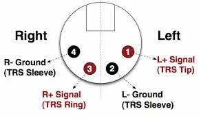
For a balanced XLR-to-TRS reference, the common mapping is Pin 1 → Sleeve, Pin 2 → Tip, and Pin 3 → Ring. This page keeps the mapping as a pinout reference only. For adapter types, unbalanced TS cases, and cable-building decisions, see the XLR to TRS connector guide.
XLR Pinout Troubleshooting: 4 Common Wiring Faults
Most XLR wiring faults fall into four types: ground-loop hum, phase cancellation, crackle/shorts, and dead lines — and all four are diagnosable with a multimeter and the pinout above.
Fault 1 — Ground Loop Hum
Symptom: A steady low-frequency buzz at 50 Hz or 60 Hz. Cause: When multiple devices sit at different ground potentials, a ground loop forms. Fix: Plug all gear into the same outlet first. If the hum persists, an audio engineer may lift the Pin 1 ground at one cable end (usually the receiving end) to break the loop — because this removes shield protection, do it only as a last resort and never on phantom-powered lines. lifting Pin 1 ground at one end follows the AES48 grounding recommendation.
Fault 2 — Phase Cancellation
Symptom: When audio sounds thin, hollow, or lacking bass, Pin 2 and Pin 3 are likely reversed at one cable end. Cause: The 180° polarity flip cancels signal when mixed with correctly-wired sources. Fix: Re-check the pinout and re-solder the wires to match Pin 2 = Hot, Pin 3 = Cold.
Fault 3 — Crackling Noises
Symptom: Intermittent crackling or static. Cause: Usually a physical short. Because stray solder strands can bridge contacts, check whether solder joints touch each other or the metal housing. Fix: Inspect whether any conductor or solder bridge is touching an adjacent pin. If the issue appears to be a solder-joint failure, follow the repair steps in the XLR soldering guide.
Fault 4 — No signal at all
Check end-to-end continuity on all three pins with a multimeter, and inspect for cold or cracked solder joints — flex the connector while testing and watch for readings that drop out. Reheat and re-solder any dull, grainy joints.
If a recurring fault traces back to the wrong part (under-rated shielding, impedance mismatch), our team can spec a correct assembly — contact us.
Frequently Asked Questions
What happens if I wire the XLR pinout wrong?
If you swap Pin 2 and Pin 3, the audio polarity reverses, causing phase cancellation when mixed with other signals. If you swap Pin 1 with Pin 2 or Pin 3, you’ll hear a loud buzz or no sound at all. Worse, when phantom power (+48V) is active, an incorrect pinout can damage a sensitive ribbon microphone — always verify wiring before powering up.
Is Pin 2 always the hot pin on XLR?
Under the modern AES14-1992 standard, yes — Pin 2 is always hot (+). Although some vintage British and American equipment wired Pin 3 hot, virtually all gear made after 1992 follows Pin 2 hot. If you’re using older equipment, check the manual and, if needed, swap Pin 2 and Pin 3 at one cable end to match. See our XLR male connector guide for more on the Pin 2 hot history.
Can I use a microphone cable for DMX lighting?
Although a 3-pin mic cable physically fits a 3-pin DMX fixture, it’s not recommended. Because microphone cable is typically 45–75 ohm while DMX requires 110-ohm impedance, using audio cable for DMX causes signal reflections — resulting in light flicker, missed cues, and strobe errors over longer runs. Use proper 110-ohm DMX cable (Belden 9729 or similar) for reliable lighting control.
Why does pinout matter for phantom power?
Because phantom power (+48V) is sent through the audio cable to power condenser microphones, correct pinout is critical. The voltage is applied equally on Pin 2 and Pin 3 relative to Pin 1 (ground) — appearing as “common mode” that balanced inputs reject naturally. If your XLR pinout is wired incorrectly or shorted, the microphone won’t receive power, or the +48V may short-circuit and damage equipment. For full phantom power coverage, see our XLR connector guide.
How do I read an XLR pinout — is it mirrored?
Yes — the female connector is a mirror image of the male. When you view the male connector with pins facing you, the numbers run one direction; when you view the female with sockets facing you, they appear reversed. Because this causes the most common wiring errors, always check the numbers molded next to each contact, and mate both connectors in a vise while soldering to keep orientation consistent.
Can a single XLR cable carry stereo audio?
Standard 3-pin XLR carries mono (single-channel) balanced audio only. If you need stereo, use two separate XLR cables — one per channel. Although some specialized 5-pin XLR connectors carry stereo (Pin 2/3 for left, Pin 4/5 for right), these are uncommon outside high-end stereo microphones. For most setups, two mono XLR cables is the standard stereo solution.
What solder should I use for XLR connectors?
Use rosin-core electronics solder only; never use acid-core solder. Leaded solder is easier to work with, while lead-free solder usually needs a slightly higher iron temperature. For soldering temperature, tinning, joint inspection, and rework steps, see the how to solder an XLR connector guide.
Conclusion
Because correct pinout is the foundation of every balanced connection, mastering the XLR pinout is essential for anyone in audio, video, or lighting. Remember the universal standard: Pin 1 = Ground, Pin 2 = Hot, Pin 3 = Cold (AES14-1992).
Browse Verchil’s XLR connector range and TRS range, or go deeper with the variant guides: 3 Pin · 4 Pin · 5 Pin · XLR male · XLR female · XLR-to-TRS. For custom cable assemblies, contact our technical team.
