
Heavy duty wire connectors are industrial connector assemblies designed to terminate conductors securely through crimp, screw, spring, cage-clamp or axial screw contacts. The correct choice depends on wire gauge, vibration level, assembly volume, current path and maintenance access. For reliable wiring, match the conductor to the contact’s specified range and use the correct stripping, crimping and inspection process.
Crimping or screw-terminating wires into a heavy duty connector — and not sure which method or wire gauge to use? Because the termination is where most field failures actually start (high-resistance joints, pulled-out wires, broken seals), getting the wiring right matters as much as choosing the connector. This guide focuses on the wire side: the four termination methods, matching wire gauge to contact, the right tools, and step-by-step wiring.
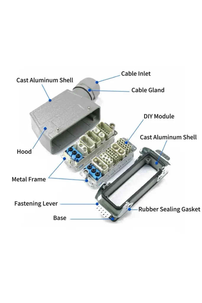
What Is a Heavy Duty Wire Connector?
A heavy duty wire connector is the wiring-side part of a heavy duty connector system. Its job is to terminate conductors safely, hold the conductor under vibration, and maintain a stable electrical path between the cable and the connector insert. In this guide, the focus is not the hood, housing or frame size; it is the termination interface: crimp contacts, screw terminals, spring clamps, cage clamps, axial screws, wire gauge matching and assembly checks.
For housing shapes, frame sizes and rectangular connector architecture, see the industrial rectangular connectors guide. For full connector selection across IP rating, locking and modular inserts, use the heavy duty connector selection guide.
Why Are Heavy Duty Wire Connectors Needed?
Why should industry transition to or insist on the use of heavy duty wire connectors, rather than hard-wire equipment?
Because the cable gland and strain relief directly protect the terminated wire, they’re the wiring-side priority: a properly torqued gland stops vibration from fracturing the conductor at the termination. For the full case on why industry uses HDC (IP protection, modularity, plug-and-play maintenance), see our heavy duty connector guide.
Safety and Stress Relief: These connectors are equipped with a strong locking mechanism to prevent accidental disconnection due to vibration. In addition, the Cable Glands used with the upper shell can ensure that the internal wire is not broken or damaged during the movement.
Heavy Duty Wire Connector Termination Methods at a Glance
| Termination Method | Best Use | Main Advantage | Main Risk |
|---|---|---|---|
| Crimp contact | High-vibration machines, repeat production, OEM cable assemblies | Repeatable connection when the correct die and tool are used | Wrong die or under-crimping creates high-resistance joints |
| Screw terminal | Field wiring, small batches, maintenance-friendly panels | Easy to assemble and rework without special crimp tooling | Loose screws under vibration if torque is not controlled |
| Spring clamp | Fast wiring, moderate vibration, compact control wiring | Maintains contact pressure without routine retightening | Wire preparation and ferrule choice must match the terminal |
| Cage clamp | Control cabinets and mixed conductor sizes | Good balance of speed, contact pressure and serviceability | Improper strip length or stranded wire preparation can reduce contact quality |
| Axial screw | High-current single-pole or power contacts | Strong mechanical clamping for larger conductors | Requires datasheet-based torque and conductor size confirmation |
Crimp vs Screw vs Spring vs Cage-Clamp Termination
Heavy duty wire connectors are usually selected by termination method before the final insert is ordered. The same housing size may accept different contact systems, so the right question is not only “how many pins?” but also “how will each conductor be terminated, inspected and serviced?”
Crimp Termination
Crimp contacts are preferred for vibration, repeatability and pre-assembled cable harnesses. The crimp tool, die, contact size and conductor range must match the manufacturer’s specification. IPC/WHMA-A-620 is a useful external reference because it defines requirements and acceptance criteria for cable and wire harness assemblies, including crimped, mechanically secured and soldered interconnections. :contentReference[oaicite:2]{index=2}
Screw Terminal Termination
Screw terminals are practical for field wiring and maintenance because they can be assembled without a dedicated crimp tool. Their weak point is installer consistency: strip length, conductor preparation and tightening torque must follow the terminal manufacturer’s datasheet.
Spring Clamp Termination
Spring clamps are useful where fast wiring and stable contact pressure matter. They reduce the need for retightening, but the conductor type, ferrule use and strip length must match the terminal design.
Cage-Clamp Termination
Cage-clamp contacts are often used in control cabinets and mixed wiring layouts. They are faster than screw terminals and more serviceable than permanent crimps, but they still require correct wire preparation.
Axial Screw Termination
Axial screw termination is typically used for larger conductors and higher-current power contacts. Do not assign a universal current value here; confirm conductor size, tightening torque and rated current from the specific contact datasheet.
How to Match Wire Gauge to Connector Contacts
Wire gauge must match the contact’s approved conductor range. A wire that is too small may not be compressed correctly; a wire that is too large may damage the contact barrel or prevent full insertion into the insert. Always confirm the conductor cross-section, insulation diameter and contact series before ordering contacts.
| Check Item | Why It Matters | What to Confirm |
|---|---|---|
| Conductor cross-section / AWG | Determines whether the contact barrel can grip the conductor correctly | Check the contact datasheet conductor range |
| Insulation diameter | Affects insertion, sealing and strain relief inside the connector | Check insert cavity and gland compatibility |
| Stranded vs solid conductor | Changes how the conductor behaves under screw, spring or crimp pressure | Confirm terminal compatibility and ferrule requirements |
| Ferrule use | Improves stranded-wire preparation for screw or spring terminals | Use only where the terminal manufacturer permits it |
| Contact plating and material | Affects contact resistance, corrosion behavior and mating life | Confirm against current, environment and mating cycle needs |
For cable jacket and outdoor sealing concerns, see the waterproof wire connectors guide. For complete HDC selection, use the heavy duty connector guide.
Tools Needed for Heavy Duty Connector Wiring
The correct tool is part of the termination system. A heavy duty connector contact should not be crimped with pliers, side cutters or an unverified universal tool. For production wiring, use the tool and die recommended for the contact series, then inspect the crimp height, insulation support and contact insertion.
- Wire stripper: strips insulation without nicking conductor strands.
- Calibrated ratchet crimp tool: controls compression and repeatability for crimp contacts.
- Correct crimp die: matches the contact barrel and conductor range.
- Ferrule crimper: prepares stranded wire for screw or spring terminals where ferrules are allowed.
- Torque screwdriver: controls screw terminal or cable gland tightening where the datasheet specifies torque.
- Contact insertion / extraction tool: prevents damage when installing or removing contacts from the insert.
- Continuity tester: verifies the final wiring path before the connector is placed into service.
How to Choose the Right Heavy Duty Wire Connector
Because choosing the connector itself — poles, IP rating, locking, environment — is covered in depth in our heavy duty connector guide, this section focuses on the wiring-side choices: select the termination method by vibration and assembly speed (crimp for high vibration, spring cage for fast assembly, axial screw for 200A+), and match the contact crimp range to your wire gauge.
Step-by-Step Heavy Duty Wire Connector Installation
Step 1 — Confirm the Wiring Diagram and Contact Layout
Before stripping any wire, confirm the pin assignment, conductor color, contact size and insert orientation. Mark power, signal, PE / ground and spare circuits separately to avoid cross-wiring during assembly.
Step 2 — Strip the Wire to the Datasheet Length
Strip only the insulation length specified by the contact or terminal manufacturer. Too short leaves insulation inside the contact zone; too long exposes conductor outside the terminal and increases short-circuit risk.
Step 3 — Terminate the Conductor
For crimp contacts, use the matched crimp tool and die. For screw, spring or cage-clamp contacts, prepare the conductor exactly as the terminal requires. Do not twist, fold or force conductor strands to fit a contact outside its approved range.
Step 4 — Inspect the Termination
Check for conductor strand damage, incomplete insertion, exposed copper, cracked insulation, incorrect ferrule size and contact deformation. For production cable assemblies, inspection criteria should be documented as part of the wiring process.
Step 5 — Insert Contacts and Verify Locking
Push each terminated contact into the insert until the retention feature is fully engaged. A contact that is not locked can back out during mating or vibration.
Step 6 — Add Strain Relief and Seal the Cable Entry
The termination should not carry cable weight or bending stress. Use the correct cable gland, clamp or strain-relief method so vibration and pulling force are absorbed by the cable jacket rather than the conductor termination.
Step 7 — Test Before Closing the Connector
Run a continuity check and verify pin-to-pin assignment before closing the hood or housing. For multi-circuit connectors, label both the cable and the connector side to simplify future maintenance.
External Resources: IPC/WHMA-A-620 cable and wire harness assembly standard
Common Termination Mistakes and How to Prevent Them
| Mistake | Failure Mode | Prevention |
|---|---|---|
| Using pliers instead of a crimp tool | Uncontrolled compression, high resistance, loose contact | Use the specified crimp tool and die |
| Wrong wire gauge | Poor conductor grip or damaged contact barrel | Match wire gauge to the contact datasheet |
| Over-stripping insulation | Exposed conductor and short-circuit risk | Use the strip length specified by the terminal |
| Skipping ferrules where required | Stranded wire deformation under screw or spring pressure | Use ferrules only when the terminal design allows or requires them |
| No strain relief | Conductor fatigue at the termination point | Clamp the cable jacket, not the conductor |
| Incorrect contact insertion | Contact backs out during mating or vibration | Confirm retention click and perform a light pull check if permitted |
Frequently Asked Questions
Which termination method is best for heavy duty wire connectors?
Crimp termination is usually preferred for high-vibration and repeat production wiring; screw terminals are practical for field maintenance; spring and cage-clamp terminals help speed up control-cabinet wiring. The best method depends on vibration level, assembly volume, conductor size and service access.
What wire gauge should be used for a heavy duty wire connector?
Use the wire gauge or conductor cross-section specified for the exact contact or terminal. Do not force a wire into a contact outside its approved range. The contact datasheet should confirm conductor size, insulation diameter and required tool or torque.
What tools are needed to terminate heavy duty connector wires?
Typical tools include a wire stripper, calibrated ratchet crimp tool, matched crimp die, ferrule crimper, torque screwdriver, contact insertion / extraction tool and continuity tester. Pliers should not be used for crimp contacts because they cannot control crimp geometry.
Should stranded wires use ferrules in heavy duty wire connectors?
Ferrules can improve stranded-wire preparation for screw or spring terminals, but they should only be used when the terminal manufacturer allows them. For crimp contacts, the conductor normally goes directly into the crimp barrel without a ferrule.
How can under-crimping be detected?
Under-crimping may show as loose conductor strands, poor pull resistance, abnormal crimp shape or increased contact resistance during testing. For production cable assemblies, define crimp inspection criteria based on the contact manufacturer’s tooling instructions and cable harness acceptance standards.
Why does strain relief matter in heavy duty wire connectors?
Strain relief prevents cable weight, vibration and bending force from being transferred directly to the conductor termination. Without it, the electrical contact may remain visually intact while conductor strands fatigue inside the connector.
Conclusion
A heavy duty wire connector is only as reliable as its termination. The connector housing may provide mechanical protection, but the actual electrical reliability depends on the conductor, contact, tool, strip length, crimp geometry, screw torque and strain relief. For high-vibration machinery, crimp contacts are usually the first option to evaluate. For field maintenance, screw terminals remain practical. For faster cabinet wiring, spring and cage-clamp contacts can reduce assembly time when the wire preparation is correct.
Verchil can support heavy duty connector wiring with crimp, screw and spring-cage termination options, as well as custom pre-wired assemblies for industrial equipment. For housing-level selection, see the heavy duty connector selection guide. For termination review, contact Verchil with the wire gauge, pole count, current rating, cable jacket diameter and operating environment.
