TRS connectors are 3-pole audio plugs available in three standard sizes: 6.35 mm (1/4 inch), 3.5 mm (1/8 inch), and 2.5 mm (3/32 inch). The three contacts—Tip, Ring, Sleeve—carry either stereo unbalanced audio (left + right + ground) or mono balanced audio (positive + negative + shield), enabling professional noise rejection over cable runs up to 30 m (100 ft).
Bought the wrong size jack for your guitar amp—again? Soldered a TRS cable that hums under any stage light? Inserted a TRRS phone headset into a TRS computer port and lost the microphone? This guide ends the confusion. You’ll learn how to identify each TRS size at a glance, decode pinouts for both stereo and balanced wiring, and solder a clean connector in 6 steps—backed by Focusrite, AES, and Neutrik specifications.
TRS in One Line (Before We Wire It)
TRS stands for Tip / Ring / Sleeve — the three conductors on the plug. This guide is the hands-on wiring reference; if you want the full anatomy of what each conductor carries, read the TRS anatomy section in our main TRS guide. Below we focus on the part that trips people up: sizes, pinout and soldering.
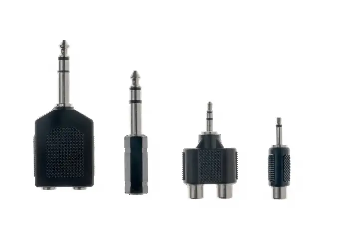
The 3 Standard TRS Connector Sizes Explained
When discussing the size of TRS joints, three industry standards are usually encountered. Although they look similar in shape, their sizes and application scenarios are quite different.
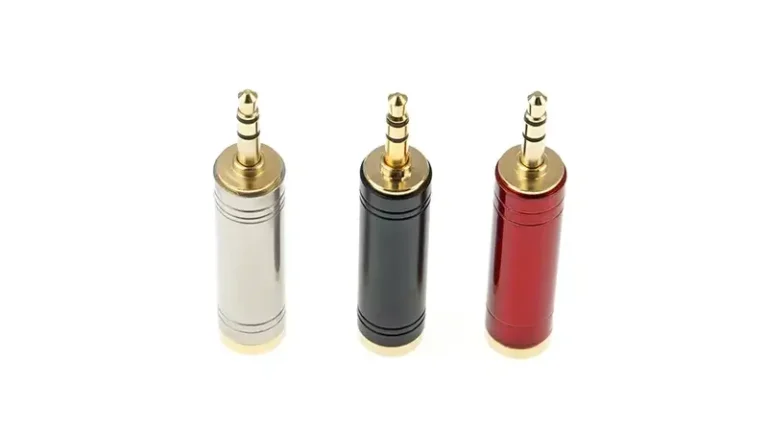
6.35 mm (1/4-inch) Phone Jack
The 6.35 mm connector—commonly called the “quarter-inch jack”—dates back to 1878, originally designed for manual telephone switchboards. It’s the ancestor of every modern audio plug and remains the professional audio standard. Typical plug length is 30–31 mm with rugged metal construction rated for 5,000+ insertion cycles.
Common uses: Electric guitars, guitar amps, mixing consoles, audio interfaces, studio headphones, patch bays.
Durability: High — designed for daily insertion and removal.
Signal level: Line-level (+4 dBu) or instrument-level (−10 dBV).
3.5 mm (1/8-inch) Mini Jack
The 3.5 mm is the most familiar TRS size globally — the standard for headphones, smartphone audio, and consumer AUX inputs since the 1980s. Typical plug length is 14 mm (standard) or 15–17 mm (extended for video applications). Smaller contact area limits durability compared to 6.35 mm.
Common uses: Headphones, earbuds, laptops, automotive AUX, portable mixers, lavalier microphones, GoPro accessories.
Durability: Medium — bent tips are common from side-load stress; design for 1,000–3,000 insertion cycles.
Signal level: Consumer line-level (−10 dBV) or headphone-level (mW range).
2.5 mm (3/32-inch) Sub-Mini Jack
The 2.5 mm is the smallest TRS size in mainstream use. Largely replaced by 3.5 mm in consumer electronics, it remains the standard for specific niche applications. Typical plug length is 11 mm with very fine contact pins.
Common uses: Two-way radio handsets, walkie-talkie headsets, camera remote shutters, hearing aids, old-style cordless phones.
Durability: Low — fragile tip; difficult to solder by hand without magnification.
Pro tip: Use a pre-terminated cable assembly rather than DIY soldering for 2.5 mm.
Bonus: 4.4 mm Pentaconn (Modern Audiophile Standard)
Worth knowing about: the 4.4 mm Pentaconn (5-pole) connector standardized in JEITA RC-8141C by the Japan Electronics and Information Technology Industries Association in 2016. It’s becoming the dominant balanced-output standard for portable audiophile players (Sony, Astell&Kern, FiiO) and high-end headphone amplifiers. Unlike traditional TRRS, the 5-pole Pentaconn properly separates left/right hot and left/right cold signals plus ground for true balanced headphone drive.
If your equipment uses 4.4 mm, do not attempt to adapt a 3.5 mm TRS — the pinout schemes are incompatible and will short-circuit the amplifier output.
| Size (Metric) | Size (Imperial) | Common Name | Plug Length | Insertion Cycles | Primary Application |
|---|---|---|---|---|---|
| 6.35 mm | 1/4 inch | Phone Jack | 30–31 mm | 5,000+ | Pro audio, guitars, amps, patch bays |
| 3.5 mm | 1/8 inch | Mini Jack | 14–17 mm | 1,000–3,000 | Headphones, smartphones, laptops |
| 2.5 mm | 3/32 inch | Sub-Mini | ~11 mm | 500–1,000 | Two-way radios, camera remotes |
| 4.4 mm | Pentaconn | ~16 mm | 5,000+ | Audiophile balanced headphones |
TRS Connector Pinout: Stereo vs Balanced Mono Wiring
To solder or repair a TRS cable correctly, you must understand the pinout. The physical size of the connector (6.35 mm vs 3.5 mm vs 2.5 mm) does not change the electrical pinout — all three sizes follow the same Tip/Ring/Sleeve electrical logic. Only the application context (stereo vs balanced) changes which signals you assign to each contact.
How to Identify the Tip, Ring, and Sleeve
Hold the plug with the metal pointing away from you. You’ll see two black insulating bands dividing the metal shaft into three conductive sections:
- Tip (T) — The pointed metal section at the very end of the plug.
- Ring (R) — The middle metal band, sandwiched between the two insulators.
- Sleeve (S) — The longest metal section closest to the cable, also acting as the structural connection to the cable handle.
Reference: SparkFun’s Audio Connector Basics provides annotated diagrams of each contact section.
Stereo Unbalanced Pinout (Headphones, AUX Cables)
For consumer headphones and unbalanced stereo line connections, the wiring follows a strict universal standard:
| Contact | Function | Convention |
|---|---|---|
| Tip | Left channel (+) | Red/white wire |
| Ring | Right channel (+) | Red wire |
| Sleeve | Common ground | Bare shield / black wire |
A handy memory aid: “Tip = Left” (T and L both come first alphabetically).
Balanced Mono Pinout (Microphones, Studio Monitors)
For studio monitor speakers, professional microphones, and line-level patching, the same TRS connector carries a balanced mono signal — the audio professional’s secret weapon against noise:
| Contact | Function | Convention |
|---|---|---|
| Tip | Hot / Positive (+) | “T = Top” of the signal |
| Ring | Cold / Negative (−) | 180° inverted copy of the signal |
| Sleeve | Shield / Ground | Drain wire and cable braid |
This is exactly the same pinout used by 3-pin XLR connectors (XLR pin 2 = Hot, pin 3 = Cold, pin 1 = Ground), which is why TRS-to-XLR adapter cables are common.
⚠️ Critical warning: Plugging a balanced mono TRS cable into a stereo TRS jack causes phase cancellation. The right-channel ring receives the inverted negative signal instead of right-channel audio, and your stereo signal collapses into a “hollow” or “missing-vocals” sound. Always verify the source/destination port type before patching.
How to Solder a TRS Connector: 6-Step Guide
Self-welding the cable allows you to customize the desired length and repair damaged equipment. Here are the steps to safely and effectively connect TRS connectors.
Tools You’ll Need
Soldering iron rated 25–40 W with a fine chisel tip (for 6.35 mm) or 15–25 W needle tip (for 3.5 mm/2.5 mm)
Rosin-core solder, 60/40 Sn/Pb or lead-free SnAgCu, 0.6–0.8 mm diameter
Wire strippers sized for 22–26 AWG audio cable
Multimeter for continuity testing before final assembly
Locking pliers or PCB vise to hold the connector steady (PanaVise 201 is the industry standard)
Heat-shrink tubing, 3:1 ratio, sized to slip over the cable jacket
Wiring Process
Step 1 — Slide the connector housing onto the cable FIRST. Before any stripping, slide the threaded connector barrel and a piece of heat-shrink tubing onto the cable. Skipping this is the #1 mistake of every beginner — you’ll only realize after soldering when the barrel can’t fit over the finished connector.
Step 2 — Strip and identify the conductors. Strip 20 mm of outer jacket. Inside a typical stereo audio cable you’ll find:
- Bare copper or braided shield → Ground (Sleeve)
- Red conductor → Right channel (Ring)
- White or black conductor → Left channel (Tip)
Strip each conductor to 4–5 mm of bare wire. Twist the strands tight before tinning.
Step 3 — Tin the conductors and solder lugs. Apply a thin coat of solder to each stripped wire end and to the connector’s solder lugs. Pre-tinning makes the final joint flow faster (lower thermal stress) and produces a stronger mechanical bond.
Step 4 — Solder the joints in this exact order:
- Sleeve (longest lug) ← bare ground/shield wire
- Ring (middle lug) ← right-channel conductor (red)
- Tip (smallest lug) ← left-channel conductor (white/black)
Apply iron to the lug for 1–2 seconds, then add solder. Total contact time should not exceed 3 seconds per joint to avoid melting the plug’s internal plastic insulator.
Step 5 — Test for continuity and shorts BEFORE assembly. Use the multimeter’s continuity mode to verify:
- Each conductor connects end-to-end (continuity beep).
- No conductor connects to another conductor (silence = good; beep = short circuit). A bridged Tip-to-Sleeve short is the most common defect — fix it now, not after sealing.
Step 6 — Heat-shrink and assemble. Slide the heat-shrink down over the solder joints and shrink with a heat gun (preferred) or lighter passed quickly. Slide the connector barrel up over the heat-shrink. Tighten the strain-relief collet onto the cable jacket (not on bare wire). Screw the barrel onto the connector body until snug.
How to Solder a TRS 1/4″ Connector Jack” (published August 2023) — visual demonstration of the 6-step process above, including pre-tinning technique and continuity testing.
TS, TRS and TRRS differ only in how many conductors they carry (2, 3 and 4). We keep the full 3-way comparison table in one place — see TRS vs TS vs TRRS — and the dedicated 4-conductor deep dive in TRS vs TRRS.
Balanced Wiring, in Brief
A balanced TRS run carries the signal twice (hot on tip, cold on ring) so interference cancels at the input — which is why balanced lines stay quiet over long distances. The full noise-rejection explanation lives in our main guide: how a balanced TRS connector rejects noise. What matters here is wiring it correctly, covered in the pinout section above.
TRS Cable Troubleshooting: 3 Most Common Field Problems
These three are the failures tied to wiring and soldering. For general TRS faults (crackle, intermittent audio, wrong signal), see Common Applications & Quick Troubleshooting.
Even with the best TRS connector pin definition knowledge, there may be problems. The following are common problems and repair methods.
Problem 1 — Constant Hum or Buzz
- Cause: Failed ground connection (Sleeve). Either the shield isn’t soldered properly, or a ground loop has formed between two grounded devices.
- Fix: Inspect the Sleeve solder joint — re-flow if it looks dull, cracked, or partially detached. For ground loops, try an audio isolation transformer (DI box) or lift one chassis ground.
Problem 2 — Intermittent Signal When Moving the Cable
- Cause: Cold solder joint (dull, grainy appearance) or a broken conductor inside the cable, usually right at the connector strain relief.
- Fix: Disassemble and re-solder the joint — proper joints are shiny and concave. Always strain-relieve the cable: the connector’s collet should grip the outer jacket, never bare conductors.
Problem 3 — “Hollow” or “Missing Vocals” Sound
- Cause: Phase cancellation, almost always from inserting a balanced mono TRS cable into a stereo TRS jack (or vice versa).
- Fix: Verify the source and destination port types. If both endpoints are confirmed balanced, check Tip/Ring weren’t reversed at one end during soldering.
Frequently Asked Questions
What are the standard TRS connector sizes?
The three mainstream TRS connector sizes are 6.35 mm (1/4 inch), 3.5 mm (1/8 inch), and 2.5 mm (3/32 inch). A fourth size, the 4.4 mm Pentaconn (JEITA RC-8141C), is gaining adoption in audiophile portable players for balanced headphone outputs. The 6.35 mm and 3.5 mm cover 95% of all consumer and professional applications.
Can I use a TS cable in a TRS jack?
Yes, but with predictable consequences. In a balanced TRS input (like a studio monitor), inserting a TS cable converts the connection to unbalanced — you lose the noise-rejection benefit but audio still passes. In a stereo TRS output (like a headphone jack), a TS plug grounds the Ring contact (right channel), so you’ll only hear left-channel mono. The reverse — TRS plug into TS jack — is also generally safe, but Ring will be shorted to Sleeve.
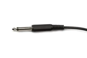
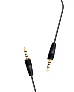
How can I tell if my plug is TS, TRS, or TRRS?
Count the black insulating bands on the metal plug shaft:
1 band = TS (2 conductors)
2 bands = TRS (3 conductors)
3 bands = TRRS (4 conductors)
4 bands = TRRRS (5 conductors, rare)
The bands separate the conductive contacts. More bands = more channels.
Is TRS better than XLR for balanced audio?
Electrically, they’re identical — both carry the same Hot/Cold/Ground balanced signal with equivalent noise rejection. The differences are mechanical: XLR has a locking latch preventing accidental disconnection (mandatory for live stage use), while TRS is faster to patch and takes less panel space. Studios commonly use both: XLR at microphone inputs, TRS at line-level patch bays.
For deep-dive XLR information, see Verchil’s XLR connector range
What gauge wire fits inside a TRS connector?
Most 6.35 mm TRS connectors accept 22–24 AWG conductors with overall cable OD of 4–8 mm. The 3.5 mm and 2.5 mm connectors are designed for fine 26–28 AWG conductors with cable OD of 2–4 mm. Always check the specific connector’s datasheet — Neutrik NP3X for 6.35 mm accepts up to 8 mm OD, while compact Switchcraft 35HDBAU for 3.5 mm tops out at 4 mm.
Why does my 3.5 mm headphone plug make a static sound when I twist it?
This is almost always dirt or oxidation on the contact surface, not a manufacturing defect. Clean the plug with isopropyl alcohol (90% or higher) on a lint-free cloth — twist gently while wiping. If the static persists, the headphone driver wires may have fractured inside the cable jacket near the plug, requiring replacement of the connector or the entire cable.
Can I make a balanced cable using a stereo TRS plug?
Yes — a 3-pole TRS plug carries balanced mono signals perfectly. Tip = Hot (+), Ring = Cold (−), Sleeve = Shield/Ground.
This is exactly how every studio uses TRS line-level connections. The cable is mechanically identical to a stereo TRS cable; only the wiring at the source/destination devices distinguishes balanced from stereo use. Always verify both endpoints support balanced operation before assuming it works.
Conclusion
Master three things and you’ll never buy the wrong TRS cable again: identify the size (6.35 mm / 3.5 mm / 2.5 mm), read the pinout (Tip = Left or Hot, Ring = Right or Cold, Sleeve = Ground), and match balanced vs unbalanced signal types at both endpoints. The electrical logic is identical across all three sizes — only the physical scale and durability change.
Browse Verchil’s complete audio connector range for both panel-mount sockets and cable-side TRS plugs, or contact our technical team for custom audio cable assemblies.
New to TRS or comparing formats? Start at our complete TRS connector guide.
