Most USB 2.0 panel mount faults trace to six causes: poor contact (oxidation), signal loss, no power, mechanical loosening, moisture corrosion, and overheating. Start by testing continuity on all four pins (VBUS, D−, D+, GND) with a multimeter, then check the pigtail and host port to isolate whether the fault is the connector, cable, or controller.
USB device dropping out, refusing to charge, or running hot at the panel? Although USB 2.0 panel mounts are known for durability, contact oxidation, wiring errors, and loose installation still cause real-world failures. Because quickly locating the fault is the difference between a 10-minute repair and hours of downtime, this guide walks through diagnosing, root-causing, and fixing the six most common USB 2.0 panel mount faults — from intermittent dropouts to moisture corrosion and overheating.
What is USB 2.0 Panel Mount Connector?
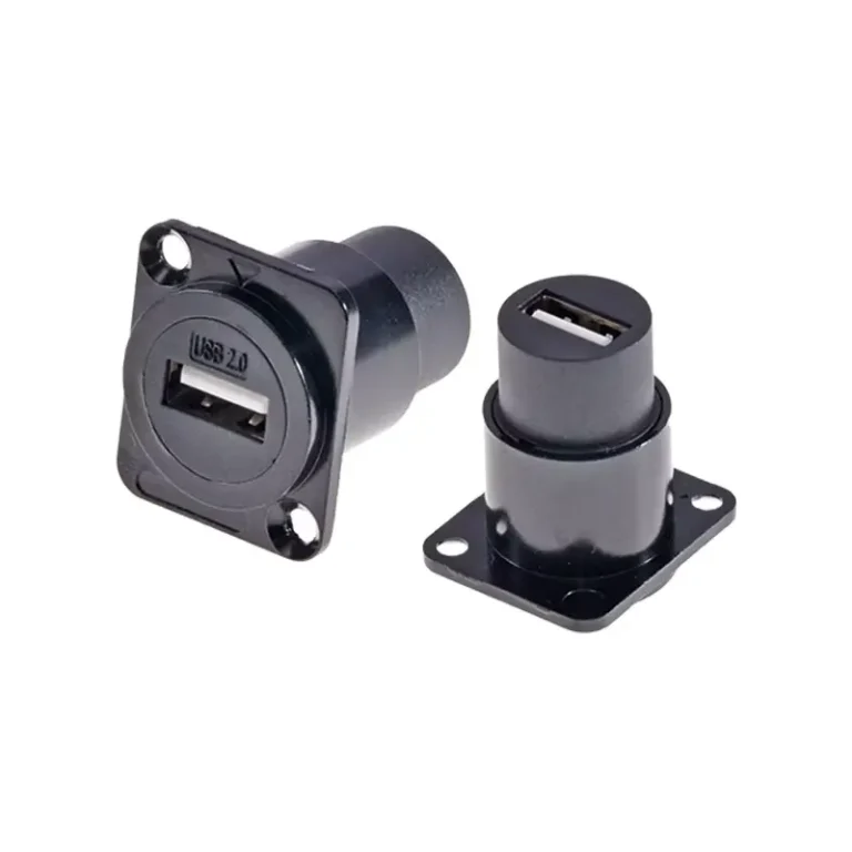
The USB 2.0 panel mount is a connector housing that flush-mounts or embeds a standard USB 2.0 port into a metal, plastic, or composite panel. Unlike an ordinary USB port soldered to a PCB, the panel mount unit uses flanges, nuts, or snaps to lock firmly into a panel cutout. It follows the USB 2.0 spec — up to 480 Mbps (Hi-Speed) and 5V/500mA — and is backward compatible with USB 1.1.
Quick description
USB 2.0 panel mount is a straight-through connector assembly, which is installed in the drilling or punching of the chassis panel. The USB Type-A or Type-B interface is exposed to the outside of the panel, and the inside is connected to the device through a short cable or a soldered terminal.
If you’re choosing between USB types, see our USB panel mount types guide.
| Feature | Standard USB Port (PCB) | USB 2.0 Panel Mount |
|---|---|---|
| Mounting Method | Soldered to PCB | Bolted / snapped into panel cutout |
| Physical Durability | Moderate (PCB stress) | High (metal/nylon flange absorbs force) |
| Cable Strain Relief | ✗ None | ✓ Built into housing |
| IP Rating Options | ✗ Usually none | ✓ IP67/IP68 models available |
| Ideal Use Case | Internal component | Front/rear panel access point |
Why do I need USB 2.0 Panel Mount?
Because a panel mount provides a clean external USB access point without exposing internal electronics to dust, liquid, or impact, engineers and makers choose it for:
- Industrial chassis and control panel – operators can insert a U disk or keyboard without opening the cabinet door.
- Custom PC and server chassis – add a front panel USB interface at any position of the non-standard chassis.
- Embedded system and Raspberry Pi project – the USB interface neatly leads to the outer wall of the chassis.
- Test and measurement equipment – provides a stable and repeatable USB connection on the desktop instrument.
- Ship, automotive and outdoor applications – waterproof USB 2.0 panel mount can withstand harsh environments.
- Medical equipment – sealed connectors meet the requirements of health standards and protection levels.
USB 2.0 Panel Mount Troubleshooting: 6 Faults & Fixes
Even if the correct USB 2.0 panel mount is selected, problems may gradually occur during use – inappropriate installation or even immediate failure. This section sorts out the six most common faults, their root causes, and the step-by-step diagnosis and repair process to help you quickly get the panel mount USB connector back to normal work.
Diagnostic tool preparation
Before starting the investigation, please prepare a USB voltage / current tester, a digital multimeter, and a known normal USB cable and equipment. It can greatly shorten the troubleshooting time by judging whether the fault is in the panel mount body, pigtail cable or host controller.
Fault 1
Device cannot be identified (poor contact / intermittent disconnection)
Fault phenomenon: The connected USB device appears and disappears repeatedly in the device manager, or the host operating system pops up “USB device not recognized” / “Unknown USB Device” error prompt intermittently.
The root cause:
- Contact pins inside USB 2.0 panel mount socket are oxidized or contaminated
- Loosening of the locking nut results in displacement of the connector housing under the action of the pull-in force
- Pigtail cable disconnection – most commonly seen in strain relief positions
- The opening size of the panel is too small, which leads to the bending deformation of the shell and affects the geometric accuracy of the contact
Repair steps:
By adjusting the multimeter to the on-off detection mode, the conductivity of four pins (VBUS, D −, D +, GND) from the panel end to the end of the tail line is checked one by one. Any disconnection can be confirmed as a disconnection fault.
Because oxidized contacts are a top cause of intermittent dropouts, examine the pins under a magnifying glass and clean them with a cotton swab dipped in 99% isopropyl alcohol — never use abrasives.
Retighten locking nuts (usually 0.3-0.5N·m) according to manufacturer’s specifications. The loosening of the connector will produce micro-arcing during insertion and extraction, which accelerates the oxidation of the contact.
If the tail wire breaks at the root of the connector, the entire panel mount assembly should be replaced. Repair splicing inside the tail line will introduce an uncontrolled impedance mutation on the D± differential pair.
Fault 2
USB signal loss / data transmission error
Failure phenomena: USB data transmission jam, data corruption, or transmission rate down to Full-Speed (12 Mbps), rather than the expected Hi-Speed (480 Mbps). CRC error occurred in the log of USB analyzer.
The root cause:
- The tail cable length exceeds the USB 2.0 signal transmission budget (5 meters), or the data cable diameter is insufficient (AWG 30 and above)
- The tail wire is unshielded or poorly shielded, and the wiring is close to the high frequency noise source (SMPS switching power supply, frequency converter, stepper motor driver)
- D± differential pair damage – Scratches or sharp-angle bends on the cable destroy the controlled impedance twisted pair structure
- The shield drain wire is not connected to the chassis ground on the panel mount
Repair steps:
Measure the total length of the cable from the host to the device. If it is more than 4 meters, replace the shorter tail cable or connect a USB2.0 active repeater in series.
Re-route the tail wire to keep it away from the noise source and at least 5 cm apart from the power cord. The tie-line belt and ferrite core are installed nearby at both ends of the tail line.
Verify that the shield drain line is reliably connected to the ground at the USB panel mount housing. The ungrounded shielding layer not only cannot isolate the noise, but also acts as an antenna.
Replace all cables with kinks, sharp corners (bending radius < 20mm) or damaged jackets.
Fault 3
No power supply / equipment can not be charged
Fault phenomenon: The USB device inserted into the panel mount USB connector is completely powerless-unable to charge, no indicator light is on, and cannot be identified by enumeration.
| Troubleshooting Form | ||
|---|---|---|
| Check Point | Expected Reading | If Out of Range |
| VBUS at panel mount face (Pin 1 to Pin 4) | 4.75 V – 5.25 V DC | Check host port fuse / polyfuse; test a different host USB port |
| Voltage drop across pigtail (VBUS end-to-end) | < 0.25 V under 500 mA load | Replace pigtail with heavier gauge (AWG 24 for VBUS/GND) |
| Contact resistance (pin to pin, no cable) | < 30 mΩ | Clean or replace connector — contacts are corroded or worn |
| GND continuity (Pin 4 to chassis) | 0 Ω (dead short) | Re-solder / re-crimp GND wire; check for broken conductor |
Fault 4
Connector mechanical looseness / rotation in panel
Troubleshooting: The USB 2.0 panel mount housing rotates or shakes in the opening when the plug is plugged, gradually pulling the internal tail wire.
The root cause:
- Locking nut loosening due to vibration (common in industrial USB panel mount installations without threaded locking agent)
- The panel opening size is too large – even if the nut has been tightened, there is still room for the shell to shake
- The anti-rotation tab is missing or broken, resulting in free rotation of the connector
Repair steps:
Re-tighten the locking nut and apply a small amount of medium-strength thread locking agent to the thread. It can be used after curing for 24 hours.
If the opening is too large, use the anti-rotation buckle groove of the connector or install a thin stainless steel gasket (shim washer) under the flange to eliminate the gap.
For high vibration environments, the industrial USB panel mount with double nuts or hexagonal flanges is used to increase the contact pressure area with the panel.
Fault 5
Water moisture and corrosion (waterproof model)
Fault phenomenon: When water enters a waterproof USB panel mount, green corrosion appears on the pins, causing intermittent failures after exposure to rain, condensation, or washdown.
The root cause:
- O-ring compression uneven-panel mounting surface uneven (welding slag residue, paint layer accumulation or sheet metal warpage)
- After pulling out the equipment, the dust cover was not re-installed in time, resulting in long-term exposure of the socket.
- The IP level is only tested when the dust cover is installed, and the sealing performance when the cable is inserted is not verified.
- O-ring aging cracking, or being squeezed out of the sealing groove due to excessive tightening
Repair steps:
Remove the connector and check the O-ring state. According to the manufacturer’s cross-reference specifications, replace the same specifications of silicone or EPDM O-ring. Apply silicone grease on the O-ring surface before re-installation-do not use petroleum-based grease, which will erode the rubber material.
Grinding or filing flat panel seal contact surface. Even if there is a gap of 0.1 mm, it is enough to destroy the IP67 seal under 1 m water pressure.
Clean the corrosion contacts with isopropanol and soft copper wire brush. If the corrosion has caused pitting of the gold plating layer, the connector must be replaced-pitting contacts will continue to accumulate water and accelerate secondary corrosion.
Confirms that the IP rating is valid in the use state of the inserted cable, not only when the dust cover is installed.
Fault 6
Connector overheating or burnt smell
Fault phenomenon: USB 2.0 panel mount shell feels hot when charging at high current, or there is a scorching odor near the connector.
The root cause:
- The tail wire VBUS and GND conductor wire diameter is not enough to carry the actual current (the device extracts more than 1 A current through the AWG 28 cable).
- The poor quality of crimping or solder joints of VBUS or GND forms a high resistance hot spot.
- Imitation connector contact coating is not up to standard-contact resistance is 5-10 times higher than the specification value.
Repair steps:
Calculate the maximum expected current. When the charging current exceeds 500 mA, VBUS and GND should use AWG 24 wire. The resistance of the AWG 28 wire is approximately 213 mΩ / m – at 1 A current, 213 mW of heat will be generated per meter of cable.
Check all crimping points and solder joints with a magnifying glass. Resolder the cold joint. Replace any crimping terminals whose tension is not up to standard.
Purchasing replacement connectors from certified regular distributors. Counterfeit USB connectors are very common on unaudited e-commerce platforms. They may use gold-free brass contacts, resulting in a contact resistance of up to 200 mΩ per pin.
Preventive maintenance recommendations
For the industrial USB panel mount installation project, it is recommended to arrange a routine inspection every year: re-tighten the lock nut, clean the contacts, replace the waterproof O-ring, and re-examine the power supply performance with the USB tester. A 10-minute preventive check avoids hours of unplanned downtime.
USB 2.0 Panel Mount Pin Definition and Wiring Guide
Before installation, it is important to fully understand the wiring of the USB 2.0 panel mount. USB 2.0 uses a 4-pin configuration (SuperSpeed differential pair without USB 3.0). The following is the definition of the standard USB Type-A base pin:
| Pin 1 | VBUS | 5V power (red wire) |
| Pin 2 | D− | Data negative / differential pair (white wire) |
| Pin 3 | D+ | Data positive / differential pair (green wire) |
| Pin 4 | GND | Ground (black wire) |
| Shell | Shield | Cable drain / panel ground (bare / braid) |
The Panel mount assembly is usually pre-connected with a 20-50 cm tail wire, and the end is a standard USB Type-A male head (used to connect the USB port of the host) or a bare wire encoded in the above color. Be sure to check the line color against the manufacturer’s datasheet – some non-brand products use non-standard line color definitions.
Note
Because each extra meter adds resistance and parasitic capacitance, keep total cable length within the USB 2.0 limit of 5 m
USB 2.0 Panel Mount Installation Steps
It’s not complicated to install a USB 2.0 panel mount connector in the right order. The following is the complete installation process:
Confirm the size of the opening
Most Type-A base panel mounts require a rectangular opening of about 14.5 mm × 6.5 mm. Please refer to the specific product datasheet – slightly different sizes from different manufacturers. Clean cut edges can be obtained using a punching die or milling machine.
Remove burrs and clean the panel
The sharp notch edge will damage the O-ring of the waterproof USB panel mount and accelerate the wear of the connector shell. Rub or polish the incision, then wipe clean with isopropyl alcohol.
Insert the connector from the outside
Push the USB socket through the opening from the outer surface of the panel. Confirm that the flange is flat and fits the panel surface without warping.
Fix with nuts or screws
Manually screw the locking nut (hexagonal or round) from the inside, then tighten according to the manufacturer’s torque specifications – typically 0.3-0.5 N·m. Do not over-tighten, otherwise it may fracture the plastic shell or deform the flange sealing surface.
Line and connect the tail line
Lead the internal tail wire to the host USB port or the motherboard pin. The bending radius of the cable is kept ≥ 20 mm to avoid stress damage to the differential pair.
Test before packaging
Insert the USB device to confirm that the power supply and data transmission are normal and then close the chassis. Use the USB tester to verify the voltage and current.
Install dust cover (if applicable)
The attached dust cover is installed when the interface is idle, which is especially suitable for outdoor or industrial USB mount panel occasions.
For detailed cutout sizing and sealing technique, see our panel mount USB socket guide.
USB 2.0 vs USB 3.0 Panel Mount: How to choose?
When purchasing the panel mount USB connector, a common question is: should I choose USB 2.0 or USB 3.0? The following comparison table helps you make a quick judgment:
| Spec | USB 2.0 Panel Mount | USB 3.0 Panel Mount |
|---|---|---|
| Max Speed | 480 Mbps | 5 Gbps (USB 3.2 Gen 1) |
| Max Current | 500 mA | 900 mA (up to 1.5 A with BC 1.2) |
| Pin Count | 4 pins | 9 pins (adds SuperSpeed pairs) |
| Cost | Lower ✓ | Higher |
| Availability of IP-rated models | Wide ✓ | Limited |
| Best For | HID devices, data loggers, charging, embedded systems | External SSDs, high-speed cameras, large file transfer |
Because USB 2.0 fully covers HID devices, data loggers, charging, and embedded boards, it meets most control-panel and kiosk needs at lower cost. Only when you need sustained high-speed throughput — external SSDs, high-speed cameras — should you step up to USB 3.0. For that option, see our USB 3.0 panel mount guide.
7 key recommendations for purchasing USB 2.0 Panel Mount
Ready to place an order? Use the following seven verified recommendations to avoid common pitfalls when purchasing USB 2.0 panel mount:
Recommendation 1 – Match the interface form according to the device type
Confirm whether you need a host-side interface (Type-A, for inserting USB devices) or a device-side interface (Type-B / Micro-B, for connecting the chassis to the PC). Mixing the two is the most common mistake in the selection.
Recommendation 2 – Confirm the panel thickness adaptation range
Each panel mount USB connector is labeled with a compatible panel thickness range (e.g. 1-6 mm). If the wall thickness of the chassis exceeds the maximum value, the locking nut will not be able to fully bite, resulting in the loosening of the connector.
Recommendation 3 – Choose the right IP level according to the environment.
Standard (unsealed) connectors can be used in indoor constant temperature environments. Where water vapor, dust or flushing are involved, a certified waterproof USB panel mount-splashproof requirement of at least IP54 should be selected, and full immersion protection requires IP67. Please confirm that the IP level is formally tested and certified according to IEC 60529.
Recommendation 4 – Assess cable length and diameter
The longer the tail line is, the more convenient the wiring is, but it also increases the signal attenuation. AWG 28 data line pair with aluminum foil shielding should be used for data-intensive applications; for high current charging applications, VBUS and GND conductors of AWG 24 should be preferred.
Recommendation 5 – Verify the material: zinc alloy vs nylon vs stainless steel
Flange material directly affects the durability and appearance. Zinc alloy has the best cost performance; stainless steel suitable for flushing or corrosive environment; nylon / PBT is lightweight and non-conductive, and is suitable for non-metallic panels or RF sensitive chassis.
Recommendation 6 – Industrial occasions need to be equipped with locking mechanism
If there is vibration in the application environment (motor, compressor, vehicle), the USB connection with standard friction will eventually fail. An industrial USB panel mount equipped with a threaded lock or bayonet-lock should be selected to physically prevent the plug from coming out on its own.
Recommendation 7 – Purchase from regular suppliers
Counterfeit products and inferior connectors are rampant in the USB market. Reliable procurement channels include Verchil, Mouser Electronics, DigiKey and Amphenol ICC (industrial grade products). When bulk purchasing, pay attention to whether the product has a RoHS compliance statement.
The main application areas of USB 2.0 Panel Mount
The versatility of the USB 2.0 panel mount makes it widely used in a wide range of industries and projects:
Industrial automation: PLC control cabinet, HMI operation panel, robot controller
Transportation: vehicle infotainment system, bus and rail transit passenger USB charging interface
Medical: sealed bedside terminal, diagnostic equipment, infusion pump interface
Consumer electronics: game arcade, custom home theater PC chassis, NAS storage devices
Business: self-service terminal (kiosk), ticket vending machine, POS cashier terminal, vending machine
Ship and outdoor: ship dashboard, outdoor kiosk, EV charging pile operation interface
Education and Maker: Raspberry Pi Chassis, Classroom Electronic Suite, STEM Lab Equipment
Frequently Asked Questions
How many holes does the USB 2.0 panel mount need to open?
Most standard USB Type-A female panel mount connectors require a rectangular hole with a width of about 14.5 mm × a height of 6.5 mm. Be sure to verify the exact size in the product mechanical drawing-flange installation model may also need to open an additional 2-4 screw holes in the four corners.
Can USB 2.0 panel mount be used only for charging (no data transmission)?
Yes. Pure charging applications only need to connect VBUS (Pin 1) and GND (Pin 4), and can choose to short-circuit D + and D − to send a dedicated charging port (DCP) signal to the device. This is a common practice in public self-service terminals and vehicle charging interfaces.
What is the maximum length of the USB 2.0 panel mount extension cable?
The USB 2.0 specification stipulates that the maximum length of a single cable is 5 meters. When panel mount is used as an extended interface, the total path from the host controller to the device (including the tail line) must be controlled within this limit. When exceeding the length, please use the USB 2.0 active repeater cable.
Is USB 2.0 panel mount compatible with USB 3.0 devices?
Compatibility-USB has complete downward compatibility. The USB 3.0 flash disk can work normally after being connected through the USB 2.0 panel mount, but the transmission rate will be limited to the USB 2.0 standard (up to 480 Mbps), rather than the 5 Gbps of USB 3.0. The physical Type-A interface is identical in shape except for the internal wiring.
What is the difference between Panel mount and chassis mount USB connector?
The two terms are usually used interchangeably. “Panel mount” emphasizes that the connector is installed in the flat panel opening through the flange and locking hardware; “Chassis mount” may refer to a connector fixed directly through a PCB bracket or chassis rail, rather than mounted on a separate panel hole. Functionally, the two have the same purpose: providing an accessible USB interface on the outer wall of the chassis.
Why does my USB 2.0 panel mount keep disconnecting?
Intermittent disconnection is almost always poor contact — oxidized pins, a loose locking nut, or a broken pigtail at the strain relief. Because each cause shows up differently, test continuity on all four pins, clean the contacts with isopropyl alcohol, retighten the nut to 0.3–0.5 N·m, and flex the pigtail while watching for dropouts. If the wire is broken at the connector root, replace the whole assembly.
Should I choose USB 2.0 or USB 3.0 panel mount?
Choose USB 2.0 for HID devices, charging, data loggers, and embedded boards — it’s cheaper and has wider IP-rated availability. Because USB 3.0 adds five pins for SuperSpeed (5 Gbps), step up only when you need sustained high throughput like external SSDs or cameras. See our USB 3.0 panel mount guide for that option.
Summary
Although a USB 2.0 panel mount is a small component, it has an outsized impact on reliability. Because the six common faults — poor contact, signal loss, no power, mechanical loosening, moisture corrosion, and overheating — all have clear root causes and fixes, mastering them slashes downtime and extends equipment life. Pair that with the 7 purchasing checks — interface type, panel thickness, IP rating, cable gauge, flange material, locking, and a reputable supplier — and you’ll avoid the most common pitfalls.
For industrial and professional builds, Verchil manufactures USB 2.0 panel mount connectors and custom cable assemblies — Type-A/B, waterproof (IP67/IP68), and locking variants, tested to spec. Explore Verchil’s USB panel mount range and full network connector lineup, or see related guides: USB panel mount types, panel mount USB socket, and USB 3.0 panel mount. For custom specs, contact Verchil’s engineering team.
