Nylon PA6 Divided Structure Waterproof Cable Gland
| Thread: | Metric, PG, G(PF), NPT thread |
| Body Material: | Nylon PA6 |
| Other Material: | NBR rubber for B.D. parts |
| Protection level: | IP68-10 Bar |
| Working temperature: | Static state:-40℃ to 100℃ Dynamic:-20℃ to 80℃ |
| Certificate | CE IP68 Rohs Reach |
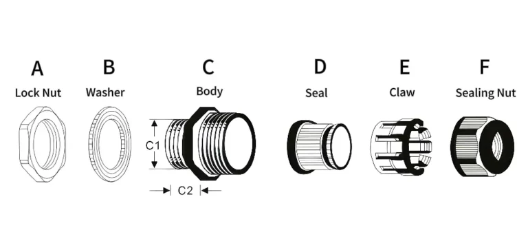
The nylon gland whose body comes apart, for the cable that cannot be threaded through one. Thirty-two catalogue rows in Metric, PG, G (BSP) and NPT, covering cable from 4 mm to 39 mm, in a PA6 body with NBR sealing parts. It exists for one reason: the cable end already carries something — a connector, a lug set, a moulded boot — that will not pass through a closed gland body. In almost every other respect it matches the united-structure line, clamping range included. The split is not free, though, and what it costs is set out below.
Series and Specifications
Thirty-two rows: twelve in Metric, ten in PG, five in G (BSP) and five in NPT. The range opens at 4 – 8 mm of cable, at M12-DS and PG7-DS, and closes at 31 – 39 mm, at M50-DS and PG42-DS. Every model number ends in DS, which is what separates it from the united-structure row of the same thread size. The other structures in the range — flexible, corrugated-pipe, metal — are compared on the cable gland category page.
Sealing is rated IP68 at 10 bar, on the same terms as the rest of the nylon range: round cable, measured outside diameter inside the printed clamping range, cap tightened down onto it. Because this body closes around the cable rather than passing over it, add one step to the sequence — seat the two halves square and closed before the cap is run down. What the ratings mean and where each applies is set out in the IP rating guide.
The trigger for reaching for this line is nearly always the same on site: the cable is already made off at one end and cutting it back is not on the table — a factory-terminated sensor lead, a pre-made assembly, a screened cable whose gland was fitted at the far end first. Thread outside diameters for all four standards are collected in the cable gland size chart.

| Model | Thread AG | Cable Range (mm) | Thread O.D (mm) | Length C2 (mm) | Spanner (mm) |
|---|---|---|---|---|---|
| PG7-DS | PG7 | 4 - 8 | 12.5 | 9 | 17 / 19 |
| PG9-DS | PG9 | 4 - 8 | 15.0 | 9 | 22 / 19 |
| PG9L-DS | PG9 | 4 - 8 | 15.0 | 12.5 | 22 / 19 |
| PG11-DS | PG11 | 6 - 10 | 18.6 | 9 | 24 / 22 |
| PG13.5-DS | PG13.5 | 7 - 12 | 20.4 | 10 | 27 / 24 |
| PG16-DS | PG16 | 8.5 - 14 | 22.5 | 10 | 30 / 27 |
| PG21-DS | PG21 | 13 - 18 | 28.3 | 12 | 35 / 33 |
| PG29-DS | PG29 | 18 - 25 | 37.0 | 12 | 45 / 42 |
| PG36-DS | PG36 | 24 - 31 | 47.0 | 15 | 56 / 52 |
| PG42-DS | PG42 | 31 - 39 | 54.0 | 20 | 65 / 62 |
| Model | Thread AG | Cable Range (mm) | Thread O.D (mm) | Length C2 (mm) | Spanner (mm) |
|---|---|---|---|---|---|
| M12-DS | M12 × 1.5 | 4 - 8 | 12 | 9 | 17 / 19 |
| M16-DS | M16 × 1.5 | 4 - 8 | 16 | 9 | 22 / 19 |
| M16L-DS | M16 × 1.5 | 4 - 8 | 16 | 15 | 22 / 19 |
| M18-DS | M18 × 1.5 | 6 - 10 | 18 | 9 | 24 / 22 |
| M18L-DS | M18 × 1.5 | 6 - 10 | 18 | 15 | 24 / 22 |
| M20-DS | M20 × 1.5 | 7 - 12 | 20 | 10 | 27 / 24 |
| M20L-DS | M20 × 1.5 | 7 - 12 | 20 | 15 | 27 / 24 |
| M25-DS | M25 × 1.5 | 12 - 18 | 25 | 12 | 33 |
| M25L-DS | M25 × 1.5 | 12 - 18 | 25 | 15 | 33 |
| M32-DS | M32 × 1.5 | 18 - 25 | 32 | 12 | 41 |
| M40-DS | M40 × 1.5 | 24 - 32 | 40 | 15 | 52 |
| M50-DS | M50 × 1.5 | 31 - 39 | 50 | 20 | 62 / 60 |
| Model | Thread AG | Cable Range (mm) | Thread O.D (mm) | Length C2 (mm) | Spanner (mm) |
|---|---|---|---|---|---|
| G3/8-DS | G3/8 | 6 - 10 | 16.662 | 10 | 22 |
| G1/2-DS | G1/2 | 7 - 12 | 20.955 | 10 | 27 / 24 |
| G3/4-DS | G3/4 | 12 - 18 | 26.441 | 12 | 33 |
| G1-DS | G1 | 18 - 25 | 33.249 | 13.5 | 41 |
| G1-1/4-DS | G1-1/4 | 24 - 32 | 41.910 | 15 | 51 / 50 |
| Model | Thread AG | Cable Range (mm) | Thread O.D (mm) | Length C2 (mm) | Spanner (mm) |
|---|---|---|---|---|---|
| NPT1/2-DS | NPT1/2 | 7 - 12 | 20.955 | 10 | 24 |
| NPT3/8-DS | NPT3/8 | 6 - 10 | 16.662 | 10 | 22 |
| NPT3/4-DS | NPT3/4 | 12 - 18 | 26.441 | 15 | 33 |
| NPT1-DS | NPT1 | 18 - 25 | 33.249 | 17 | 41 |
| NPT1-1/4-DS | NPT1-1/4 | 24 - 32 | 41.984 | 17 | 52 |
What the Split Costs You Is the Two Ends of the Catalogue
Set these tables beside the united-structure tables and the middle of the range is the same part in two pieces. Leaving the long-thread L variants aside, the two lines share twenty-seven thread sizes, and twenty-five of those clamp exactly the same cable — same range, same figures, no derating for the joint. The two that differ are PG7 and M12, and both differ the same way: 4 – 8 mm here against 3 – 6.5 mm there.
The cost sits at the ends. The united-structure line offers sixteen different clamping bands. The divided line offers ten.
Three of the six missing bands are below 4 mm: 2.5 – 4.8, 2.5 – 6.0 and 3 – 6.5. Small cable is where the divided structure runs out first, and it is also why PG7-DS and M12-DS start at 4 mm rather than 3 — those are the only two of the twenty-seven shared thread sizes that clamp differently from their united-structure twins. Two more missing bands are above 39 mm: 32 – 44 and 40 – 55. So the divided line covers 4 to 39 mm where the united line covers 2.5 to 55.
The sixth missing band is 16 – 21 mm, and it leaves no hole in the coverage. A 20 mm cable simply moves up a row: M32-DS, PG29-DS, G1-DS and NPT1-DS all take 18 – 25 mm. Inside their own limits the tables are continuous — Metric and PG run without a gap from 4 mm to 39 mm, G and NPT from 6 mm to 32 mm. What the split costs is reach at the two ends, not resolution in the middle.
Where These Glands Are Used
Retrofit and maintenance work in industrial plant is the first case, and it is the one this structure was made for. A machine is being re-cabled, a drive is being swapped, a sensor loom is being extended — and the cable arrives with a plug, a lug set or a heat-shrunk boot already on the end of it. A closed gland body would mean cutting the termination off and remaking it. A divided body goes on where the cable already is. These glands sit alongside the rest of our industrial automation connector solutions.
The second case is pre-made assemblies going into outdoor and communication enclosures. Where the cable is cut, terminated and tested in the workshop and only the enclosure end is made off on site, the divided gland is what lets the finished assembly through a roadside cabinet or a rooftop housing without being taken apart. That work is covered in our communication and outdoor equipment connector solutions.
Send the thread designation of the entry, the measured outside diameter of the cable over its sheath, and what is already fitted to the cable end, and we will come back with the row. More on the factory behind these parts.
Nylon PA6 Divided Structure Waterproof Cable Gland FAQ
What voltage is this cable gland rated for?
Cable glands do not carry a voltage rating, and no figure on this page is one. The gland seals the entry and holds the sheath; the insulation rating belongs to the cable, and the clearances belong to the enclosure and to whatever the cable lands on inside it. Two things do rule this line out, though, and both are worth settling before the size. If the cable is screened or armoured and the screen or armour has to be bonded at the entry, that needs an unbroken metal path from the gland into the panel, which a polymer body cannot provide — the nickel-plated brass line is the one to look at. And if the enclosure sits in a certified hazardous area, the question is not the material but whether the part carries the certification the installation calls for, which is a documentation question rather than a catalogue one.
Can I use this with armoured or screened cable?
Mechanically, yes: the clamp holds a sheathed armoured cable like any other, on its measured outside diameter. Electrically, no. This gland cannot terminate wire armour or braid, and it cannot make the continuous 360-degree bond that a screened installation depends on, because that needs an unbroken metal path from the screen through the gland body into the panel. For that, the nickel-plated brass line is the right family. One measuring point either way: combing the braid back over the sheath adds to the diameter at exactly the point where the gland clamps, so measure the cable after it has been prepared, not before.
What is the difference between a divided cable gland and a split grommet?
A gland is a threaded fitting. It screws into a tapped hole or is held by a lock nut in a plain one, and it clamps the cable itself, so the seal and the strain relief are the same part. A split grommet is a frame or an insert that fills an opening: it seals around the cable, but it is sized by the opening it fits rather than by a thread designation, and holding the cable is usually somebody else's job. Split grommet frames with their own ingress ratings do exist, and they earn their place where a lot of cables share one large cut-out. The quick test when reading a datasheet is this — if the part is specified by a thread designation and ships with a lock nut, it is a gland; if it is specified by a rectangular cut-out size, it is not.